An electronic rearview mirror system and vehicle
An electronic rearview mirror and video image technology, which is applied in the direction of closed-circuit television systems, televisions, electrical components, etc., can solve the problems that the irradiation range of the five-category mirror cannot be met, the vehicle cannot meet the installation requirements, and the irradiation range cannot be covered. Large-scale commercial production and use, avoiding misjudgment and dizziness, and avoiding the effects of visual fatigue
- Summary
- Abstract
- Description
- Claims
- Application Information
AI Technical Summary
Problems solved by technology
Method used
Image

Examples
Embodiment 1
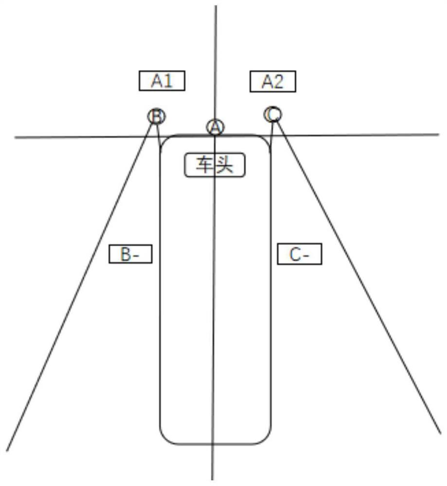
[0072] Embodiment 1 proposes an electronic rearview mirror system, such as figure 2 As shown, the camera 170 of the electronic rearview mirror system includes at least three cameras, and the three cameras are specifically: a front camera A, a left rear camera B, and a right rear camera C. Among them, the front camera A is limited by the central axis of the vehicle, and is installed in the middle or roof of the vehicle. The lens of the front camera A adopts a wide-angle camera with a horizontal shooting angle of 90-150 degrees. The optical axis of the front camera A It is tilted downward by 20-50 degrees, and the front camera A illuminates the ground. The illuminated area includes two parts, which are respectively defined as the A1 area and the A2 area. The left rear camera B and the right rear camera C are respectively installed on the left and right sides of the front of the vehicle. The lenses of both adopt wide-angle cameras with a horizontal shooting angle of 90-150 degre...
Embodiment 2
[0083] Embodiment 2 proposes an electronic rearview mirror system, such as Figure 5As shown, the camera 170 of the electronic rearview mirror system includes at least 5 cameras, specifically, the 5 cameras are: a front camera A, a lower left camera B, a lower right camera C, a left rear camera D and a right rear camera E. Among them, the front camera A is limited by the central axis of the vehicle, and is installed in the middle or roof of the vehicle. The lens of the front camera A adopts a wide-angle camera with a horizontal shooting angle of 90-150 degrees. The optical axis of the front camera A It is tilted downward by 20-50 degrees, and the front camera A illuminates the ground. The illuminated area includes two parts, which are respectively defined as the A1 area and the A2 area. The lower left camera B and the lower right camera C are respectively installed on the left and right sides of the front of the vehicle. The images taken by the two take the central axis of the...
PUM
 Abstract
Description
Claims
Application Information
 - R&D
- Intellectual Property
- Life Sciences
- Materials
- Tech Scout
- Unparalleled Data Quality
- Higher Quality Content
- 60% Fewer Hallucinations
Browse by: Latest US Patents, China's latest patents, Technical Efficacy Thesaurus, Application Domain, Technology Topic, Popular Technical Reports.
© 2025 PatSnap. All rights reserved.Legal|Privacy policy|Modern Slavery Act Transparency Statement|Sitemap|About US| Contact US: help@patsnap.com