A Zero Focus Compensation Method for Intelligent Laser Cutting Head

A technology of laser cutting head and compensation method, which is applied in laser welding equipment, metal processing equipment, welding equipment, etc., can solve the problems of affecting the focusing accuracy, increasing the difficulty of use by on-site debugging personnel, etc., to ensure accuracy and reduce hands-on use. Difficulty, the effect of reducing the difficulty of getting started

Active Publication Date: 2021-11-30
江苏迅镭激光科技有限公司
View PDF8 Cites 0 Cited by
  • Summary
  • Abstract
  • Description
  • Claims
  • Application Information

AI Technical Summary

Problems solved by technology

No zero focus compensation will affect the follow-up focusing accuracy
Compensation is done on the computer side of the host computer, which leads to the continuity of the parameters of the cutting head. If the cutting head is repaired or replaced, the parameters need to be re-adjusted, which increases the difficulty of use by on-site debuggers.

Method used


Image

  • A Zero Focus Compensation Method for Intelligent Laser Cutting Head
  • A Zero Focus Compensation Method for Intelligent Laser Cutting Head
  • A Zero Focus Compensation Method for Intelligent Laser Cutting Head

Examples


Embodiment 1

[0044] see Figure 1-4 , a zero-focus compensation method for an intelligent laser cutting head, comprising the following steps:

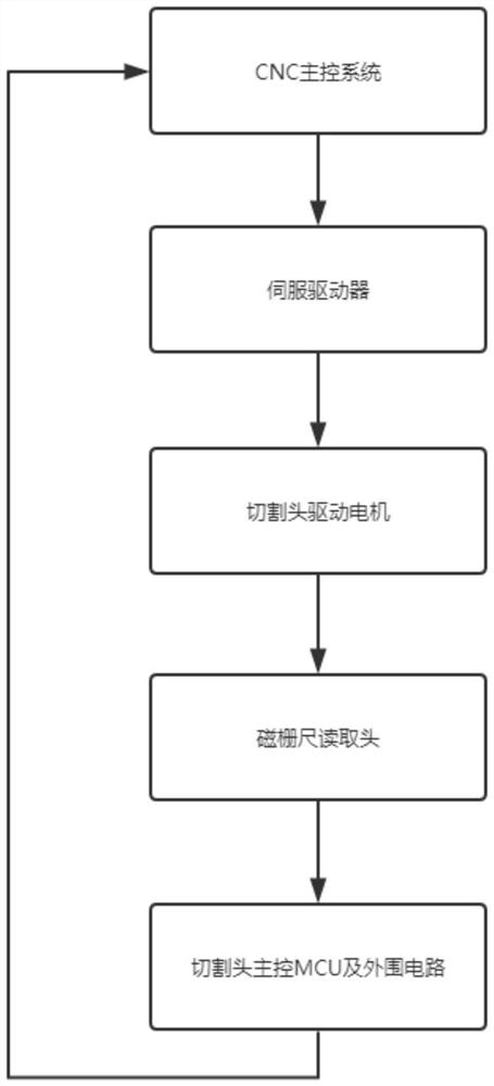
[0045] S1. The laser cutting head is driven by the cutting head moving device to move up and down, and a magnetic scale is installed on the moving section of the cutting head moving device;

[0046] S2. Read the magnetic grid signal of the magnetic scale through the main control unit MCU, and determine the zero position reference;

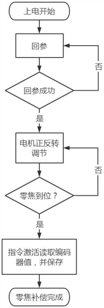
[0047] S3. Control the working of the cutting head moving device to drive the laser cutting head to move up and down, thereby driving the focusing lens barrel to move up and down, and stop the movement when the reference returns to the zero point position reference, and record the stay height position of the focusing lens barrel as Y1;

[0048] S4. Control the cutting head moving device to drive the laser cutting head to move up and down, mark the steel plate under the laser cutting head through the laser cutting head,...


PUM


Abstract

The invention discloses a zero-focus compensation method for an intelligent laser cutting head, which comprises the following steps: installing a magnetic scale on the moving section of the cutting head moving device; reading the magnetic grid signal of the magnetic scale through a main control unit MCU, And determine the zero point position reference; control the cutting head moving device to drive the laser cutting head to move up and down, thereby driving the focusing lens barrel to move up and down, and stop the movement when the zero point position reference is found by reference. The zero-focus compensation method of the intelligent laser cutting head of the present invention can perform a compensation calibration for the deviation between the assembly zero-focus and the theoretical zero-focus, and add the compensation value into each focusing and reference process to realize the function of eliminating errors . The invention performs zero focus compensation calibration at the factory, which reduces the difficulty of operation and ensures the continuity and consistency of zero focus compensation parameters. Difficulty of use.

Description

technical field [0001] The invention specifically relates to a zero-focus compensation method for an intelligent laser cutting head. Background technique [0002] The components of the laser cutting machine cutting head are: nozzle, focusing lens and focus tracking system. The laser cutting machine focus tracking system is generally composed of a focus cutting head and a tracking sensor system. The cutting head is composed of light guide focusing, water cooling, air blowing and mechanical adjustment; the sensor is composed of sensing element and amplification control part. The tracking system is completely different according to the different sensing elements. Here, there are mainly two types of tracking systems, one is the capacitive sensor tracking system, also known as the non-contact tracking system. The other is an inductive sensor tracking system, also known as a contact tracking system. [0003] The theoretical zero focus of the laser cutting head is required to be...

Claims


Application Information

Patent Timeline
Patent Type & Authority Patents(China)
IPC IPC(8): B23K26/046B23K26/38
CPCB23K26/046B23K26/38
Inventor 丁方浩刘德军
Owner 江苏迅镭激光科技有限公司
Why Eureka
Try Eureka