
Stamping die for flanging processing of plate-shaped parts

A stamping die and flanging technology, which is applied in the direction of forming tools, manufacturing tools, metal processing equipment, etc., can solve the problems of increasing the difficulty of making molds, roughening of boards, and inability to remove them

Inactive Publication Date: 2020-04-17
长沙金鸿顺汽车部件有限公司
View PDF5 Cites 0 Cited by
  • Summary
  • Abstract
  • Description
  • Claims
  • Application Information

AI Technical Summary

Problems solved by technology

[0003] These methods either consume more manpower, or increase the difficulty of mold making, and most of them are made of iron for the plate. Once the plate is replaced with aluminum, stainless iron or stainless steel, aluminum powder or iron powder will be produced during the flanging process. , cannot be removed, and will eventually lead to roughening of the board

Method used


Image

  • Stamping die for flanging processing of plate-shaped parts
  • Stamping die for flanging processing of plate-shaped parts
  • Stamping die for flanging processing of plate-shaped parts

Examples


Embodiment Construction

[0021] Specific embodiments of the present invention will be described in detail below in conjunction with the accompanying drawings.

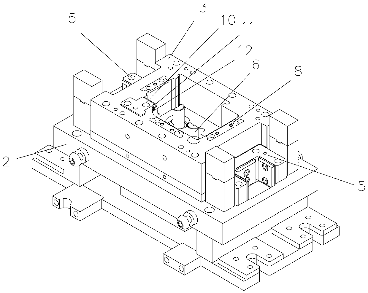
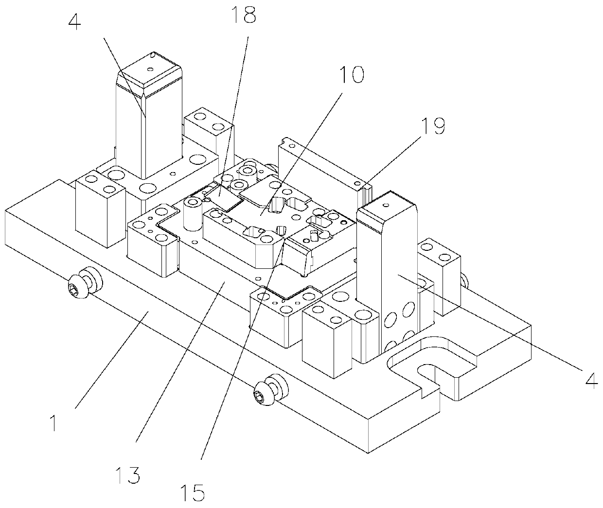
[0022] Such as Figure 1-4 As shown, a stamping die for flanging processing of plate-shaped parts includes an upper mold base 1 and a lower mold base 2, and the lower mold base 2 is provided with a lower template 3. Both sides of the upper mold base 1 are respectively provided with guide columns 4, and the lower template 3 is provided with matching guide blocks 5 with guide grooves.

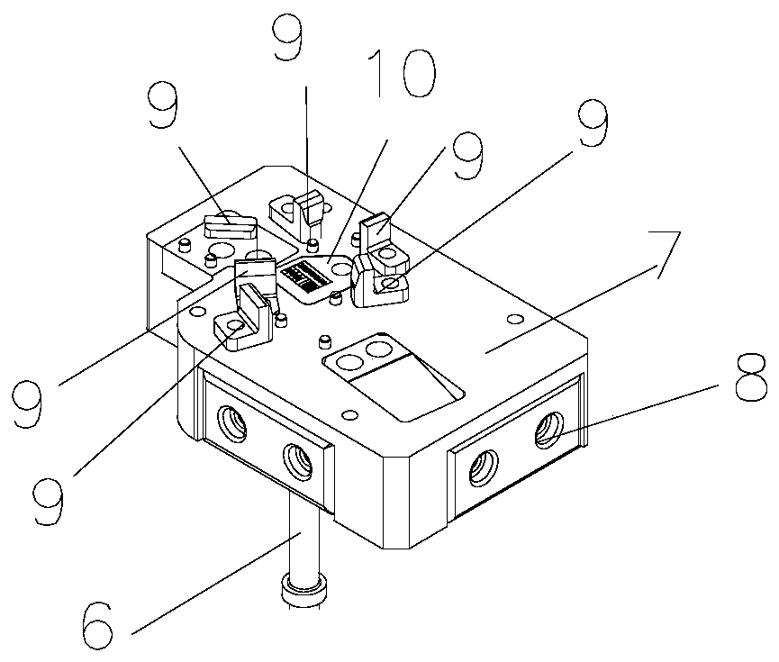
[0023] The lower formwork 3 is provided with an installation groove, and the part corresponding to the installation groove on the lower formwork 3 on the lower mold base 2 is provided with a lower forming block 7 moving up and down through the lifting spring 6, and the lower forming block 7 is respectively provided with Wear-resistant plates 8, matching wear-resistant plates 8 are provided at corresponding positions on the side wall of the mounting groove on the...


PUM


Abstract

The invention discloses a stamping die for flanging processing of plate-shaped parts, wherein when the stamping die is used for flanging of aluminum parts and stainless iron or stainless steel workpieces, the workpieces cannot be galled. The stamping die comprises an upper die base and a lower die base; a lower die plate is arranged on the lower die base; a mounting groove is formed in the lower die plate; a lower forming block which moves up and down is movably arranged on the part, corresponding to the interior of the mounting groove in the lower die plate, of the lower die base through a jacking spring; a plurality of positioning pieces for limiting the position of a workpiece are arranged on the lower forming block; a flanging cutter block is arranged on the lower die plate and at theto-be-flanged part of the workpiece; a flanging rolling shaft parallel to a bending line at the flanging position of the workpiece is rotationally arranged in the flanging cutter block; a mounting notch is formed in the cutting edge of the flanging cutter block; the periphery of the flanging rolling shaft is exposed out of the mounting notch, the side face, used for forming a workpiece, of the flanging cutter block is tangent to the periphery of the flanging rolling shaft, a mounting plate is arranged on the upper die base, an upper forming block matched with the lower forming block in shape is arranged on the mounting plate, and an upper cutter block matched with the flanging cutter block is detachably arranged on the upper forming block.

Description

technical field [0001] The invention relates to a stamping die, in particular to a stamping die for flanging a plate-shaped part. Background technique [0002] During the stamping and flanging process of the plate, it is required that there is no roughness on the edge after the flanging. The existing improvement methods include: 1. Wipe off the oil and waste on the surface of the die; 2. Increase the smoothness of the fillet part of the die and polish it; 3. Increase the hardness of the die insert and use conventional coating treatment; 4. .If the bending gap of the mold is too small, adjust the bending gap of the upper and lower dies; 5. The bending radius R of the punch is too small, increase the bending radius of the punch; 6. The surface of the raw material is not smooth, clean and level the raw material. [0003] These methods either consume more manpower, or increase the difficulty of mold making, and most of them are made of iron for the plate. Once the plate is repl...

Claims


Application Information

Patent Timeline
IPC IPC(8): B21D37/10B21D37/12B21D19/02
CPCB21D19/02B21D37/10B21D37/12
Inventor 尹飞
Owner 长沙金鸿顺汽车部件有限公司
Learn More