


Quick Research
Generate reliable direction feasibility study reports for your R&D in just a few steps.

Technical Q&A
Discover and master advanced knowledge NOW. Basics, ideas, possibilities, all at once.

Find Solutions
As an expert in R&D theories, this can generate solutions to your technical problems instantly.

Evaluate Feasibility
Analyze your overall solution with one click, know your potential R&D risks in advance.

Monitor Landscape
Get weekly tech updates, stay abreast of the latest tech innovations and key insights.
Medical internal medicine liquid pumping device
A technology of internal medicine and liquid barrel, which is applied in the direction of pumping and pumping system, hypodermic injection equipment, suction container, etc. It can solve the problems of difficulty in grasping the puncture stability and puncture angle, damage to the myocardium, and unfavorable use, so as to achieve good patient and protection patients, the effect of ensuring stability
- Summary
- Abstract
- Description
- Claims
- Application Information
AI Technical Summary
Problems solved by technology
Method used
Image


Examples
Embodiment 1
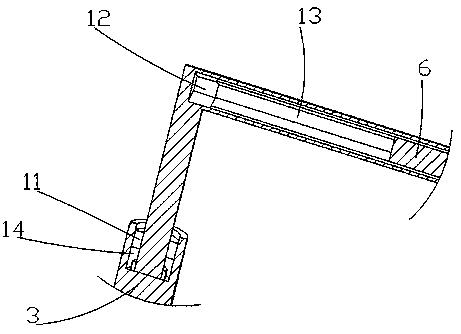
[0036] Such as Figure 1-6As shown, a medical internal medicine pumping device of this embodiment includes a bottom plate 1, a liquid pumping structure 2 and a puncture needle 9, the top of the bottom plate 1 is fixedly connected with a support column 3, and the top of the support column 3 is movably connected with an L-shaped rod 4, The top of the support column 3 is provided with a straight groove 14, and the inner bottom of the straight groove 14 is rotationally connected with the L-shaped rod 4 through a fixedly connected bearing. Sliding connection, the circular rubber 11 increases the rotation resistance of the L-shaped rod 4, so that the L-shaped rod 4 can be stable after rotation, and will not rotate independently. The polygonal rubber sleeve 13 is connected, and the polygonal rubber sleeve 13 is fitted and slidably connected to the polygonal sliding rod 7. The L-shaped rod 4 increases the sliding resistance of the polygonal sliding rod 7, effectively preventing the po...
Embodiment 2
[0038] Embodiment two is a further improvement on embodiment one, as Figure 1-6 As shown, the liquid pumping structure 2 includes a horizontal pipe 21, a sleeve 22, a piston 210, a rod 23, a one-way valve 24, a straight pipe 25, a cover plate 26, a liquid pumping barrel 29, a piston 210, a spring 211, a leather cup 212, an arc Shaped groove 213, ball 214 and straight rod 215, horizontal pipe 21 is fixedly connected with flexible pipe 5, and the left end of horizontal pipe 21 is fixedly connected with leather cup 212, and leather cup 212 is provided with arc-shaped groove 213, and the right end of horizontal pipe 21 is fixedly connected There is a straight rod 215, the side wall of the straight rod 215 is fixedly connected with a spring 211, and the spring 211 is fixedly connected with a ball 214 that fits and slides with the arc groove 213, and the right end of the horizontal tube 21 is fixedly connected with a sleeve 22, and the inside of the sleeve 22 A piston 210 is fitted...
Embodiment 3
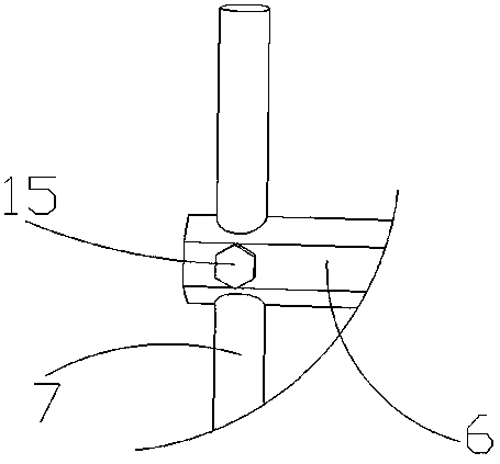
[0040] Embodiment three is a further improvement on embodiment one, as Figure 1-6 As shown, the positioning structure includes a push bolt 88 and a rubber sheet 87, the push bolt 88 is threadedly connected with the mounting block 810, the push bolt 88 is fixedly connected with the rubber sheet 87, the rubber sheet 87 is slidably connected with the disc 86, the push bolt 88 and the threaded rod 81 outer ends are all fixedly connected with hexagonal nut 85, through angle adjustment structure 8 middle disk 86 is convenient to rotate along slide bar 7, and disk 86 is convenient to drive arc splint 83 to rotate, and the clamping angle of arc splint 83 can be adjusted. Adjust according to the puncture angle of the puncture needle 9, and improve the practicability of the device, which is beneficial to actual use. At the same time, the push bolt 88 in the positioning structure pushes the rubber sheet 87 to contact the disc 86, thereby fixing and limiting the disc 86, ensuring The sta...
PUM
 Abstract
Description
Claims
Application Information
 - R&D Engineer
- R&D Manager
- IP Professional
- Industry Leading Data Capabilities
- Powerful AI technology
- Patent DNA Extraction
Browse by: Latest US Patents, China's latest patents, Technical Efficacy Thesaurus, Application Domain, Technology Topic, Popular Technical Reports.
© 2024 PatSnap. All rights reserved.Legal|Privacy policy|Modern Slavery Act Transparency Statement|Sitemap|About US| Contact US: help@patsnap.com