


Quick Research
Generate reliable direction feasibility study reports for your R&D in just a few steps.

Technical Q&A
Discover and master advanced knowledge NOW. Basics, ideas, possibilities, all at once.

Find Solutions
As an expert in R&D theories, this can generate solutions to your technical problems instantly.

Evaluate Feasibility
Analyze your overall solution with one click, know your potential R&D risks in advance.

Monitor Landscape
Get weekly tech updates, stay abreast of the latest tech innovations and key insights.
Synchronization signal block position indication method, network equipment and terminal equipment
A synchronization signal and terminal equipment technology, applied in the field of information processing, can solve the problem that the terminal equipment cannot be further guaranteed to save terminal measurement time and power consumption, and achieve the effect of saving measurement time and power consumption
- Summary
- Abstract
- Description
- Claims
- Application Information
AI Technical Summary
Problems solved by technology
Method used
Image


Examples
Embodiment 1
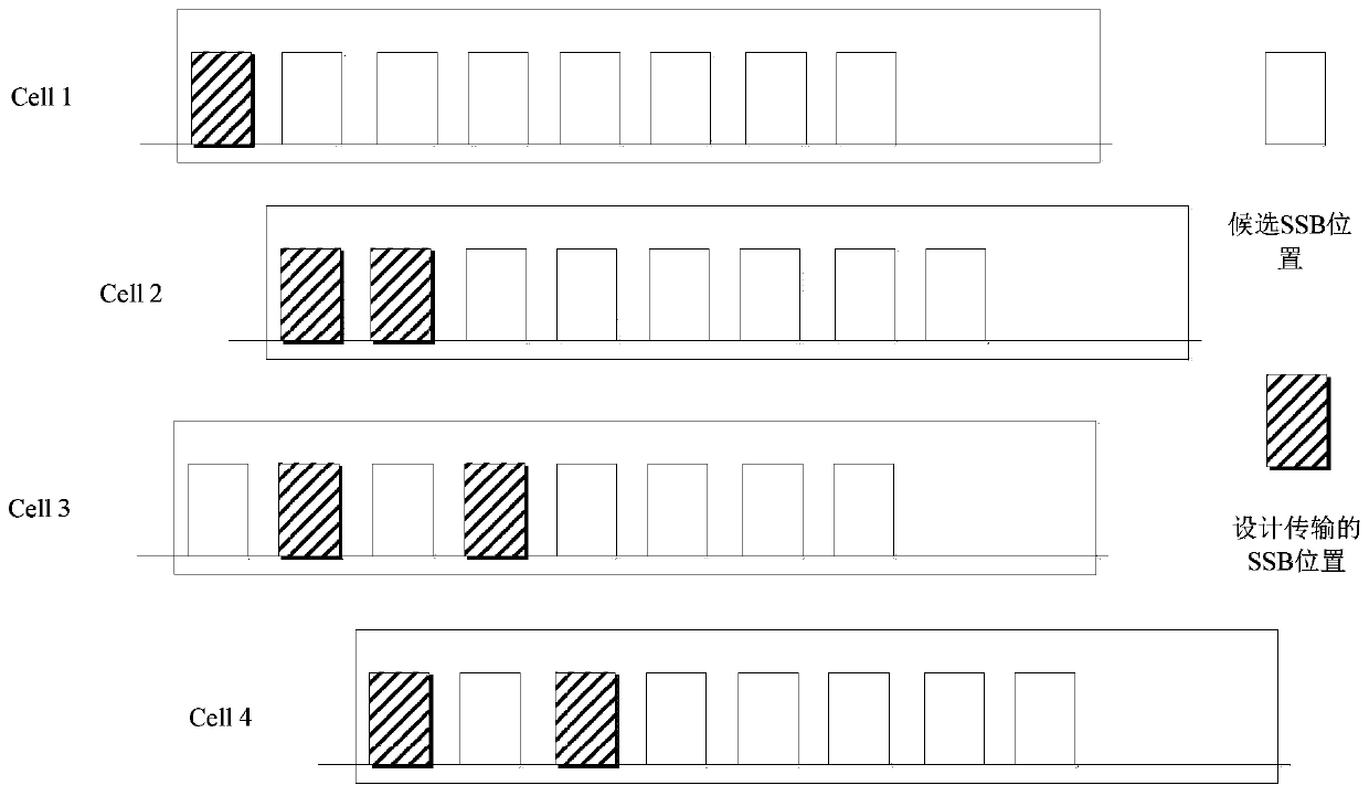
[0034] This embodiment provides a method for indicating the position of a synchronization signal block, such as figure 1 shown, including:
[0035] Step 101: Determine the transmission position of the synchronization signal block of at least one cell of the first type;
[0036] Step 102: Send the transmission position of the synchronization signal block of the at least one first-type cell to a terminal device through signaling; wherein, the terminal device is located within a range of a second-type cell managed by the network device.
[0037] Here, the network device may be a base station, for example, eNB, gNB, etc., or other network devices, as long as it can provide the terminal device with the function of accessing the mobile communication network.
[0038] It should be further noted that the first type of cell refers to a cell adjacent to the cell where the terminal device is located, which may be an adjacent cell.
[0039] In addition, it can also be understood that th...
Embodiment 2
[0092] This embodiment provides a method for indicating the position of a synchronization signal block, which is applied to a terminal device, such as Figure 4 shown, including:
[0093] Step 401: Receive the transmission position of the synchronization signal block of at least one first-type cell sent by the network device through signaling;
[0094] Step 402: Based on the transmission position of the synchronization signal block of the at least one first type cell, measure the synchronization signal block of the at least one first type cell.
[0095] Here, the network device may be a base station, for example, eNB, gNB, etc., or other network devices, as long as it can provide the terminal device with the function of accessing the mobile communication network.
[0096] For non-CA (carrier aggregation) scenarios, the cell where the terminal device is located may be called a second-type cell, and the second-type cell may also be called the serving cell of the terminal device; ...
Embodiment 3
[0135] This embodiment provides a network device, such as Figure 5 shown, including:
[0136]The processing unit 51 is configured to determine the transmission position of the synchronization signal block of at least one first-type cell; and control to send the transmission position of the synchronization signal block of the at least one first-type cell to the terminal device through signaling; wherein, The terminal device is located within the range of the second type of cell managed by the network device;
[0137] The communication unit 52 is configured to send signaling to the terminal device.
[0138] Here, the network device may be a base station, for example, eNB, gNB, etc., or other network devices, as long as it can provide the terminal device with the function of accessing the mobile communication network.
[0139] It should be further noted that the first type of cell refers to a cell adjacent to the cell where the terminal device is located, which may be an adjac...
PUM
 Abstract
Description
Claims
Application Information
 - R&D Engineer
- R&D Manager
- IP Professional
- Industry Leading Data Capabilities
- Powerful AI technology
- Patent DNA Extraction
Browse by: Latest US Patents, China's latest patents, Technical Efficacy Thesaurus, Application Domain, Technology Topic, Popular Technical Reports.
© 2024 PatSnap. All rights reserved.Legal|Privacy policy|Modern Slavery Act Transparency Statement|Sitemap|About US| Contact US: help@patsnap.com