
Anti-collision transformer with high safety

A transformer and safety technology, applied in the direction of transformer/inductor shell, etc., can solve the problems of low safety, easy leakage, poor anti-collision effect of transformers, etc., to improve safety, avoid secondary accidents, and solve anti-collision effects poor effect

Pending Publication Date: 2020-04-14
PINGDINGSHAN POWER SUPPLY ELECTRIC POWER OF HENAN
View PDF5 Cites 0 Cited by
  • Summary
  • Abstract
  • Description
  • Claims
  • Application Information

AI Technical Summary

Problems solved by technology

[0003] The existing transformers have poor anti-collision effect, and are prone to electric leakage after impact, resulting in low safety

Method used


Image

  • Anti-collision transformer with high safety
  • Anti-collision transformer with high safety
  • Anti-collision transformer with high safety

Examples


Embodiment 1

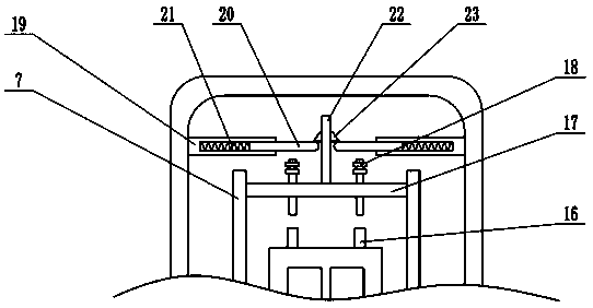
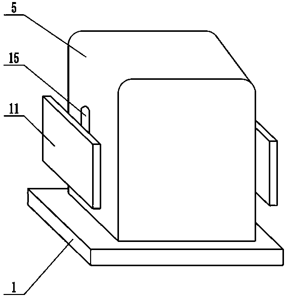
[0020] see Figure 1-3 , in the embodiment of the present invention, a high-safety anti-collision transformer includes a base 1, a casing 5, a transformer body 8 and a buffer plate 11, the base 1 is buried in the ground, and a fixing assembly is installed on the bottom of the base 1 , the fixed component includes a fixed pile 2, a fixed plate 3 and a fixed rod 4, the lower surface of the base 1 is fixedly connected with the fixed pile 2, the lower end of the fixed pile 2 is fixedly connected with the fixed plate 3, and the lower surface of the fixed plate 3 is distributed with fixed Rod 4, the stability of the device can be improved by using the fixing assembly, so that the device can be more firmly connected to the ground. The upper surface of the base 1 is detachably mounted with a shell 5, and the inside of the shell 5 is provided with a fixed plate 6. The fixed plate 6 There are two in total, which are arranged symmetrically on the left and right. A transformer body 8 is i...

Embodiment 2

[0022] On the basis of Embodiment 1, a positioning mechanism is installed inside the casing 5, and the positioning mechanism includes a fixed cylinder 19, a movable rod 20 and a positioning spring 21, and the side wall of the casing 5 is fixedly connected with a fixed cylinder 19, and there are two fixed cylinders 19. , arranged symmetrically left and right, a movable rod 20 is installed inside the fixed cylinder 19, and the movable rod 20 is slidingly connected with the fixed cylinder 19, and the movable rod 20 can slide left and right in the fixed cylinder 19, and a positioning spring 21 is installed inside the fixed cylinder 19, when When being hit, lifting plate 17 moves upwards, thereby drives fixed plate 22 to move upwards, utilizes positioning tooth 23 to push movable rod 20, movable rod 20 is moved to both sides, after positioning tooth 23 moves to the top of movable rod 20, utilizes Positioning teeth 23 block the lifting plate to prevent the lifting plate 17 from falli...


PUM


Abstract

The invention relates to the field of power equipment. More particularly, the present invention relates to an anti-collision transformer with high safety; the transformer comprises a base, a shell, atransformer body and buffer plates, a fixing assembly is installed at the bottom of the base. The shell is detachably mounted on the upper surface of the base; fixed plates are arranged in the shell;the transformer body is installed between the two fixed plates; the fixed plates are fixedly connected with the base; a sliding groove is formed in the top of each fixed plate; a sliding plate is mounted in each sliding groove; the sliding plates are slidably connected with the fixed plates; a through groove is formed in the side wall of the shell; the side wall of each fixed plate is fixedly connected with a sleeve; a sliding rod is mounted in each sleeve; each sleeve is sleeved with a buffer spring, the end of each sliding rod is fixedly connected with one buffer plate, when the buffer plates are impacted, the buffer springs can be used for absorbing part of energy, the buffer effect and the anti-collision effect are achieved, the safety of the equipment is improved, meanwhile, the transformer body is powered off, and secondary accidents caused by electric leakage of the transformer body are avoided.

Description

technical field [0001] The invention relates to the field of power equipment, more specifically, a high-safety anti-collision transformer. Background technique [0002] Transformer is a device that uses the principle of electromagnetic induction to change AC voltage. The main components are primary coil, secondary coil and iron core (magnetic core). The main functions are: voltage conversion, current conversion, impedance conversion, isolation, voltage stabilization (magnetic saturation transformer), etc. According to the purpose, it can be divided into: power transformers and special transformers (electric furnace transformers, rectifier transformers, power frequency test transformers, voltage regulators, mining transformers, audio transformers, intermediate frequency transformers, high frequency transformers, impact transformers, instrument transformers, electronic transformers , reactors, transformers, etc. [0003] The existing transformer has poor anti-collision effec...

Claims


Application Information

Patent Timeline
Patent Type & Authority Applications(China)
IPC IPC(8): H01F27/02
CPCH01F27/02
Inventor 邱骏刘林曼李肖可陈运政雷飒贾子昊艾晓雨刘智强王得道李晓航靳耀珂
Owner PINGDINGSHAN POWER SUPPLY ELECTRIC POWER OF HENAN
Learn More