Traffic light and lane matching method and device and electronic equipment
A matching method and technology for traffic lights, applied in the field of image processing, can solve the problems of tediousness, low efficiency, and poor universality of matching algorithms.
- Summary
- Abstract
- Description
- Claims
- Application Information
AI Technical Summary
Problems solved by technology
Method used
Image


Examples
Embodiment 1
[0032] refer to figure 1 It is a schematic structural diagram of an electronic device 100 for implementing the method and device for matching traffic lights and lanes according to an embodiment of the present invention. The electronic device 100 includes one or more processors 102, one or more storage devices 104, and an input device 106 , an output device 108 and an image acquisition device 110 , these components are interconnected via a bus system 112 and / or other forms of connection mechanisms (not shown). It should be noted that figure 1 The components and structure of the electronic device 100 shown are only exemplary, not limiting, and the electronic device may have figure 1 Some components shown may also have figure 1 Other components and structures are not shown.
[0033] The processor 102 can be implemented in at least one hardware form of a digital signal processor (DSP), a field programmable gate array (FPGA), and a programmable logic array (PLA), and the process...
Embodiment 2
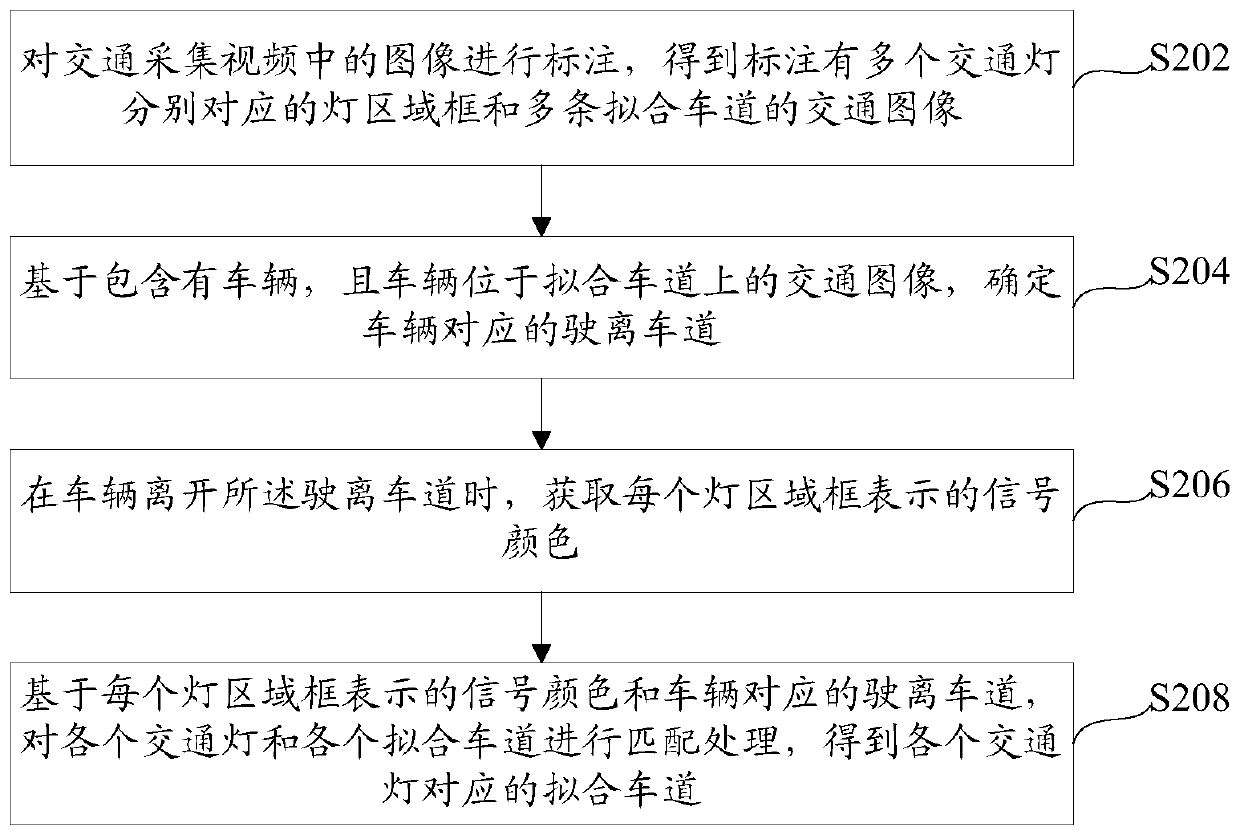
[0040] see figure 2 A schematic flowchart of a method for matching traffic lights and lanes is shown, the method mainly includes steps S202 to S206:
[0041] In step S202, the images in the traffic collection video are marked to obtain a traffic image marked with light area frames corresponding to a plurality of traffic lights and a plurality of fitting lanes.
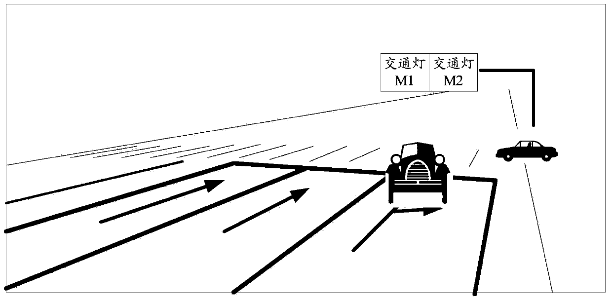
[0042] Traffic collection video can be understood as traffic monitoring video, which can be collected by collection equipment in practical applications, wherein the collection equipment can include equipment with shooting functions (such as cameras, etc.), and the collection equipment can be deployed within the preset range of traffic lights In the area, the traffic acquisition video including traffic lights and lanes can be collected in real time by adjusting the shooting angle of the acquisition device; the light area frame can be understood as the bounding box of the traffic light in the image of the traffic acquis...
Embodiment 3
[0089] Regarding the method for matching traffic lights and lanes provided in Embodiment 2, the embodiment of the present invention provides a matching device for traffic lights and lanes, see Figure 9 A structural schematic diagram of a matching device for a traffic light and a lane is shown, the device mainly includes the following parts:
[0090] The labeling module 902 is configured to label images in the traffic collection video, and obtain traffic images labeled with light area frames corresponding to multiple traffic lights and multiple fitted lanes.
[0091] The determination module 904 is configured to determine the departure lane corresponding to the vehicle based on the traffic image containing the vehicle and the vehicle is located on the fitting lane.
[0092] The color acquisition module 906 is configured to acquire the signal color represented by each light area frame when the vehicle leaves the departure lane.
[0093] The matching module 908 is configured to...
PUM
 Abstract
Description
Claims
Application Information
 - Generate Ideas
- Intellectual Property
- Life Sciences
- Materials
- Tech Scout
- Unparalleled Data Quality
- Higher Quality Content
- 60% Fewer Hallucinations
Browse by: Latest US Patents, China's latest patents, Technical Efficacy Thesaurus, Application Domain, Technology Topic, Popular Technical Reports.
© 2025 PatSnap. All rights reserved.Legal|Privacy policy|Modern Slavery Act Transparency Statement|Sitemap|About US| Contact US: help@patsnap.com