A bearing ring numerical control machine tool

A bearing ring, CNC machine tool technology, used in metal processing machinery parts, maintenance and safety accessories, metal processing and other directions, can solve problems such as inconvenience for workers to maintain machine tools, reduce vibration, reduce radiation range, and improve machining accuracy. Effect

Active Publication Date: 2020-11-10
海宁上通优必胜轴承有限公司
View PDF5 Cites 0 Cited by
  • Summary
  • Abstract
  • Description
  • Claims
  • Application Information

AI Technical Summary

Problems solved by technology

[0004] The bearing ring CNC machine tool mentioned above is the second-generation machine tool of our company, but in the actual use process, it is found that due to the long fuselage, the workers need to take care of a large range of lengths. Even if two machine tools are set face to face, one worker can It can only take care of two machines at the same time, which is not convenient for workers to maintain the machine tool

Method used


Image

  • A bearing ring numerical control machine tool
  • A bearing ring numerical control machine tool
  • A bearing ring numerical control machine tool

Examples


Embodiment Construction

[0030] The present invention will be described in further detail below in conjunction with the accompanying drawings.

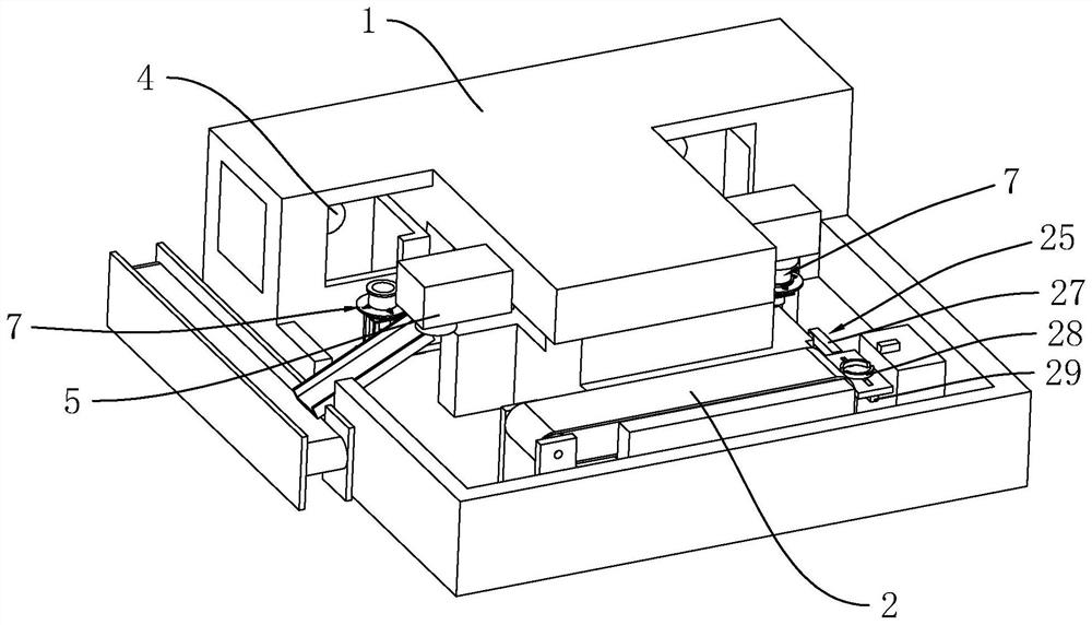
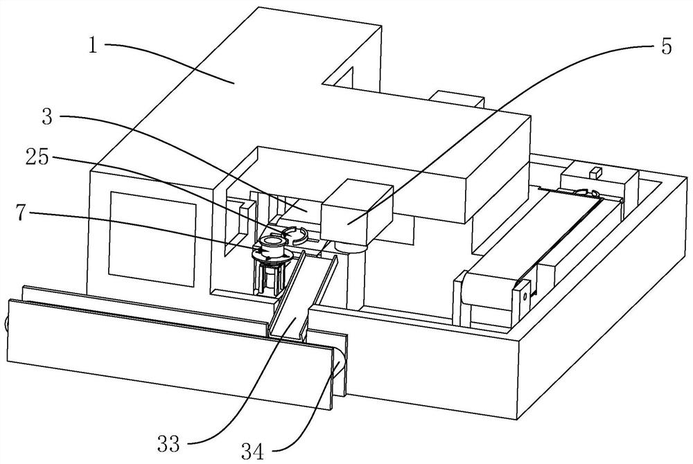
[0031] combine figure 1 and figure 2As shown, a bearing ring numerical control machine tool includes a body 1, a feed conveyor belt 2 is arranged on the body 1, and a return conveyor belt 3 is arranged on one side of the feed conveyor belt 2, the transmission directions of the two are parallel and opposite, and the return Knife turrets 4 are arranged at both ends of the side of the material conveyor belt 3 facing away from the feed conveyor belt 2, and a manipulator 5 corresponding to the turret 4 is arranged on the body 1, and the turret 4 is arranged on the body 1, and the turret 4 is fixedly distributed with many cutters 6 (not shown in the figure) used for bearing ring processing, and the axial direction of the cutter tower 4 is perpendicular to the transmission direction of the return conveyor belt 3. At this time, the setting range of the entire fusel...


PUM


Abstract

The invention discloses a numerically-controlled machine tool for a bearing ring, and relates to the technical field of bearing machining equipment. A purpose of the invention is to solve the problemof inconvenient management by workers due to too large radiation range in processing of the bearing ring through the machine tool. The technical scheme of the invention is that the numerically-controlled machine tool for the bearing ring comprises a machine body, which is provided with a feeding conveying belt, wherein a material returning conveying belt is arranged on one side of the feeding conveying belt, the transmission directions of the feeding conveying belt and the material returning conveying belt are parallel and opposite, cutter towers and mechanical arms for respectively grabbing abearing ring to the corresponding cutter tower so as to be processed are arranged at the two ends of the side, back to the feeding conveying belt, of the material returning conveying belt correspondingly, various cutters for processing the bearing ring are fixed to the cutter tower, and the axial directions of the cutter tower is perpendicular to the conveying direction of the material returningconveying belt. The numerically-controlled machine tool of the invention is reasonable in structure, substantially reduces the operation radiation range during bearing ring processing, and can be conveniently maintained by a worker.

Description

technical field [0001] The invention relates to the technical field of bearing processing equipment, in particular to a bearing ring numerical control machine tool. Background technique [0002] Bearing is an important part of contemporary mechanical equipment. Its main function is to support the mechanical rotating body, reduce the friction coefficient during its movement, and ensure its rotation accuracy. Bearings are divided into many categories, and rolling bearings are only one of them. Rolling bearings mainly include three parts: outer ring, inner ring, rolling elements and cages. In the production process of rolling bearings, the four parts are produced and processed separately, and then the four parts are to assemble. [0003] For example, the patent whose publication number is CN108380905A discloses a bearing ring CNC machine tool, including a fuselage, the left and right sides of the fuselage are respectively provided with cutters for processing bearing rings, and...

Claims


Application Information

Patent Timeline
Patent Type & Authority Patents(China)
IPC IPC(8): B23D79/00B23Q7/04B23Q11/00
CPCB23D79/00B23Q7/047B23Q11/00
Inventor 陈炳华
Owner 海宁上通优必胜轴承有限公司
Why Eureka
Try Eureka