
Supporting pad capable of shaping heel part

A shapeable heel technology, applied in the field of medical devices, can solve the problems of pressure injury, inability to fix with ice packs, unfavorable recovery of affected limbs, etc., achieve the effect of preventing pressure injury, simple and compact structure, and easy to promote and use

Inactive Publication Date: 2020-04-14
THE FIRST PEOPLES HOSPITAL OF CHONGQING LIANG JIANG NEW AREA
View PDF18 Cites 0 Cited by
  • Summary
  • Abstract
  • Description
  • Claims
  • Application Information

AI Technical Summary

Problems solved by technology

[0002] Regardless of whether a lower limb fracture patient uses a lower limb raising pad or not, the patient's heel is in a drooping state when lying in bed, and there is no support point for the heel, which makes the patient feel uncomfortable or painful, which is not conducive to the recovery of the affected limb. Rehabilitation, also prone to foot drop or pressure injury
The traditional way to solve this problem is to put cotton pads or sponge objects on the heel, but this method is not easy to fix, and it is easy to shift when the patient moves, and may even cause secondary damage to the affected limb
When the heel is injured, the heel needs to be raised for treatment, and sometimes even ice is applied to it. The traditional method is to use the above-mentioned cotton pad or sponge to raise the heel, and then use an ice pack The ice pack is used to apply ice to it, but this method cannot fix the ice pack on the heel well, and it is easy to make the ice pack not in good contact with the affected part during the patient's activities

Method used


Image

  • Supporting pad capable of shaping heel part

Examples


Embodiment Construction

[0020] In order to describe the technical content, structural features, achieved goals and effects of the present invention in detail, the following will be described in detail in conjunction with the embodiments and accompanying drawings.

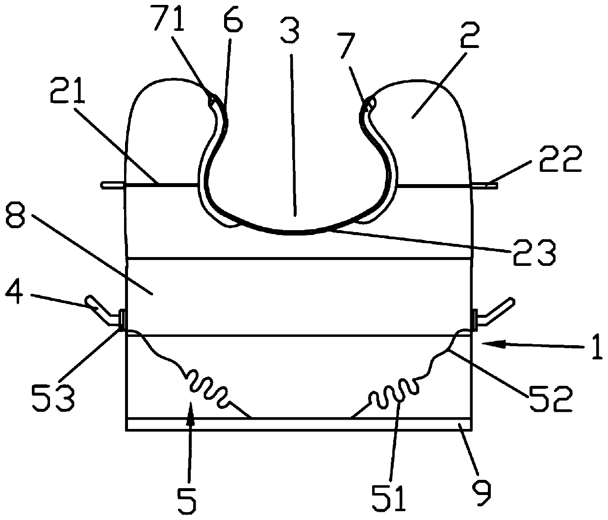
[0021] see figure 1 , a shapeable heel support pad includes a base 1, a support portion 2 and a heel accommodation chamber 3, a rotating handle 4 is installed in the center on both sides of the base 1, and springs 5 ​​are provided on both sides of the base , one end of the spring 5 is connected to the rotating handle 4, the other end is fixedly installed on the bottom of the base 1, the support part 2 is fixedly installed above the base 1, and both sides are provided with connecting Rod 21, the middle of the support part 2 is recessed to form a heel accommodation chamber 3, and a surface layer 6 and an ice bag cover 7 are arranged between the support part 2 and the heel accommodation chamber 3.

[0022] In this embodiment, the upper end o...


PUM


Abstract

The invention discloses a supporting pad capable of shaping a heel part. The supporting pad comprises a base, a supporting part and a heel part containing cavity. Rotary handles are arranged in the middles of the two sides of the base. Springs are arranged on the two sides in the base. One end of each spring is connected with a rotary handle, and the other end is fixedly arranged at the bottom ofthe base. The supporting part is arranged above the base, and connecting rods are arranged on the two sides. The middle of the supporting part is sunken to form the heel part containing cavity. A surface layer and an ice bag sleeve are arranged between the supporting part and the heel part containing cavity. According to the invention, spiral springs drive a support to move to change the height ofthe base; a stretching rod pushes the inner side to move left and right; the size of the heel part containing cavity is changed; the ice bag sleeve is arranged on the inner side, and a deformable icebag can be placed in the ice bag sleeve; the requirement of different diseases for the height of the lifting pad and the requirement of different foot sizes for the size of the heel part containing cavity are met; the heel part is effectively fixed; pressure injuries and foot drop are prevented; and the size of the heel part containing cavity can be adjusted during ice compress, and the ice bag makes contact with an affected part as much as possible, so that a good ice compress effect is achieved.

Description

technical field [0001] The invention relates to the technical field of medical devices, in particular to a shapeable support pad for the heel. Background technique [0002] Regardless of whether a lower limb fracture patient uses a lower limb raising pad or not, the patient's heel is in a drooping state when lying in bed, and there is no support point for the heel, which makes the patient feel uncomfortable or painful, which is not conducive to the recovery of the affected limb. Rehabilitation, but also prone to foot drop or pressure injury. The traditional way to solve this problem is to put cotton pads or sponge objects on the heel, but this method is not easy to fix, and it is easy to shift when the patient moves, and may even cause secondary damage to the affected limb. When the heel is injured, the heel needs to be raised for treatment, and sometimes even ice is applied to it. The traditional method is to use the above-mentioned cotton pad or sponge to raise the heel, ...

Claims


Application Information

Patent Timeline
Patent Type & Authority Applications(China)
IPC IPC(8): A61G7/075A61F7/10
CPCA61F7/10A61F2007/0045A61G7/0755
Inventor 邓美菊卿群英倪艳霞
Owner THE FIRST PEOPLES HOSPITAL OF CHONGQING LIANG JIANG NEW AREA
Learn More