control device
A technology of a control device and a controller, which is applied to secure communication devices, data exchange through path configuration, bus network, etc., can solve problems such as time-consuming communication relays
- Summary
- Abstract
- Description
- Claims
- Application Information
AI Technical Summary
Problems solved by technology
Method used
Image
Examples
no. 1 Embodiment approach -
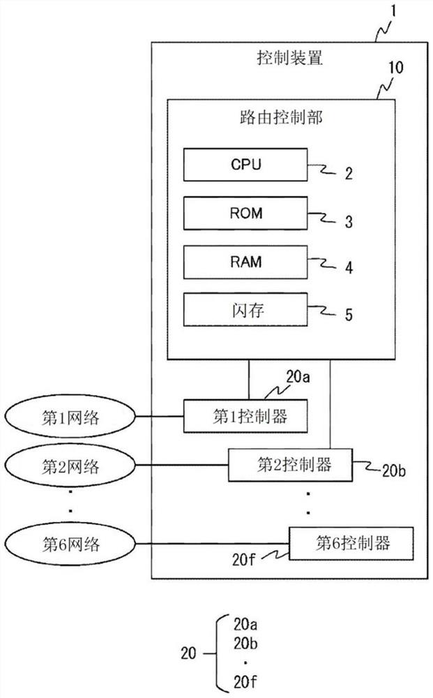
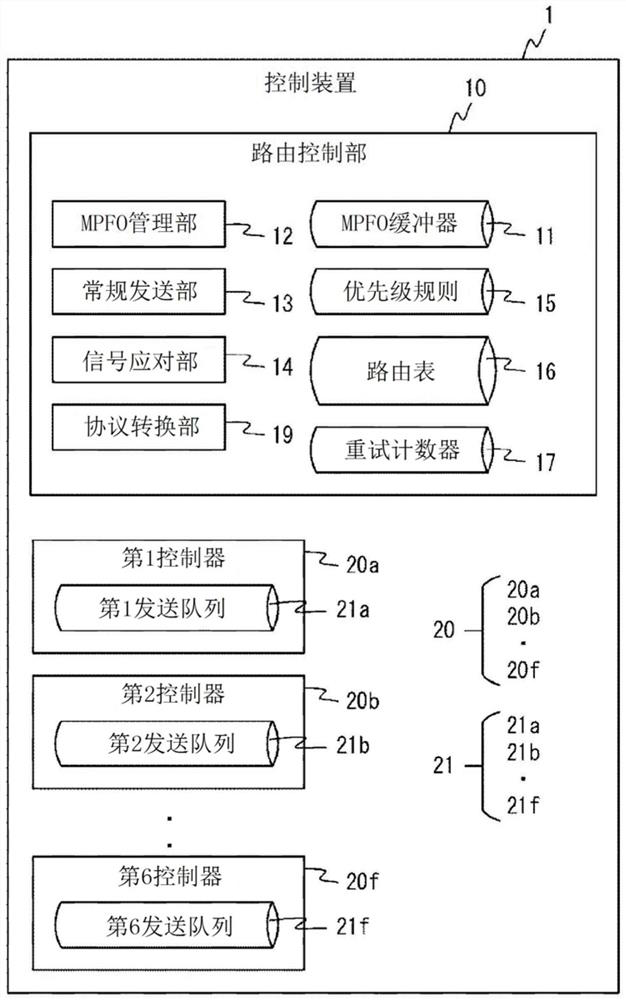
[0029] Below, refer to Figure 1 to Figure 11 , the first embodiment of the control device of the present invention will be described. The control unit is connected to at least 2 networks. In this embodiment, the description is made in the form of connection to six networks.
[0030] (hardware configuration)
[0031] figure 1 It is a hardware configuration diagram of the control device 1 . The control device 1 is connected to a plurality of networks, that is, six first to sixth networks. The six networks are, for example, CAN (Controller Area Network), TCP / IP, and LIN (Local Interconnect Network). However, the communication protocol used in each network is not limited to this, and MOST (Media Oriented System Transport) and FlexRay can also be connected. In addition, the communication protocol used in each network may be the same. In addition, the control device 1 may be connected to two to five networks, or may be connected to seven or more networks.
[0032] The contr...
Deformed example 1
[0078] In the first embodiment described above, a retransmission target flag is added to each frame stored in the MPFO buffer 11, and whether or not it is a retransmission target frame is determined based on the value of the flag. However, the management of the information indicating whether or not it is a retransmission object is not limited to this, and various methods can be used. For example, a table for managing retransmission target frames may be provided.
[0079] Figure 12 It is a diagram showing an example of the retransmission management table 18 for managing retransmission target frames. The retransmission management table 18 stores, for each frame ID, information indicating whether or not it is a retransmission target, for example, "Yes" or "No". Figure 12 The shown example shows the case where only the frame ID "10" is subject to retransmission. Reissue management table 18 in Figure 10 Write "Yes" in the processing in S340, in Figure 11 "No" is written in...
Deformed example 2
[0081] The routing control unit 10 may include a buffer sorting unit that deletes untransmitted frames that have passed a predetermined time or more since reception. Figure 13 It is a flowchart showing the operation of the buffer sorting unit. The buffer sorting unit is executed every predetermined time, for example, every 100 ms by Figure 13 Programs that demonstrate actions.
[0082] Figure 13 In S361, first, the buffer sorting unit judges whether or not a frame whose predetermined time or more has elapsed since reception is stored in the MPFO buffer 11 . When it is determined that the MPFO buffer 11 stores a frame whose reception has elapsed for a predetermined time or more, the buffer sorting unit proceeds to S362, and if it determines that there is no frame in the MPFO buffer 11 for which a predetermined time has elapsed since the reception. In the case of frames, end by Figure 13 Programs that demonstrate actions. In S362, the buffer sorting unit deletes the cor...
PUM
 Abstract
Description
Claims
Application Information
 - Generate Ideas
- Intellectual Property
- Life Sciences
- Materials
- Tech Scout
- Unparalleled Data Quality
- Higher Quality Content
- 60% Fewer Hallucinations
Browse by: Latest US Patents, China's latest patents, Technical Efficacy Thesaurus, Application Domain, Technology Topic, Popular Technical Reports.
© 2025 PatSnap. All rights reserved.Legal|Privacy policy|Modern Slavery Act Transparency Statement|Sitemap|About US| Contact US: help@patsnap.com


