Molecular spectroscopy cell with resonant cavity

A technology of resonant cavity and water molecule, applied in the field of molecular spectroscopy chamber with resonant cavity

Pending Publication Date: 2020-04-10
TEXAS INSTR INC
View PDF3 Cites 1 Cited by
  • Summary
  • Abstract
  • Description
  • Claims
  • Application Information

AI Technical Summary

Problems solved by technology

Miniaturizing such devices while maximizing the cross-secti...

Method used


Image

  • Molecular spectroscopy cell with resonant cavity
  • Molecular spectroscopy cell with resonant cavity
  • Molecular spectroscopy cell with resonant cavity

Examples


Embodiment Construction

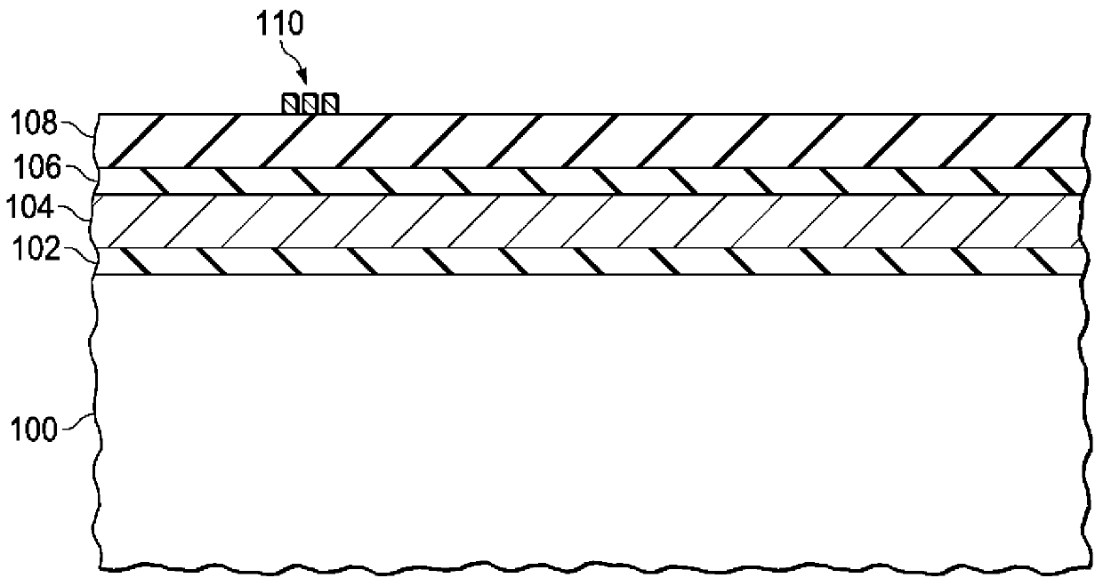
[0010] Embodiments described herein are directed to a spectroscopic chamber comprising a cavity formed in a substrate, such as a semiconductor substrate. The cavity contains a dipolar molecule (eg water molecule) at a relatively low pressure. The cavity is hermetically sealed, and a radio frequency (RF) signal is injected into the cavity at a frequency approximately equal to the absorption frequency of dipole molecules in the cavity. For water molecules, the absorption frequency is 183.31 GHz. The described spectroscopy can be used in various applications such as a clock generator to generate a 183.31 GHz clock signal that does not vary with temperature, pressure, or process.

[0011] The pressure inside the cavity is relatively low. In the example of water molecules, this pressure may be approximately 0.1 millibar (mbar), although a range of acceptable pressures is possible. For example, if molecular argon is used, the pressure may be several atmospheres. Too high a press...


PUM


Abstract

A device includes a substrate (100) that includes a resonant cavity (125). The resonant cavity (125) includes dipolar molecules that have an absorption frequency. The resonant cavity (125) resonates at a frequency that is equal to the absorption frequency of the dipolar molecules. The device further includes a first port (110) on the resonant cavity (125) configured to receive a radio frequency (RF) signal.

Description

Background technique [0001] Various applications may include hermetic cavities formed in semiconductor structures. In one application, a chip-scale atomic clock can include a selected vapor at low pressure in a sealed cavity. Miniaturizing such devices while maximizing the cross-sectional area to interact with molecules in the cavity is a challenge. Contents of the invention [0002] In one embodiment, an apparatus includes a substrate including a resonant cavity. The resonant cavity includes dipolar molecules with absorption frequencies. The resonant cavity resonates at a frequency equal to the absorption frequency of the dipolar molecules. The device further includes a first port on the resonant cavity configured to receive a radio frequency (RF) signal. [0003] An apparatus includes a substrate including a resonant cavity. The resonant cavity includes dipolar molecules with absorption frequencies. The resonant cavity resonates at a frequency equal to the absorption...

Claims


Application Information

Patent Timeline
IPC IPC(8): H01L27/24H01Q17/00
CPCG01N22/00H01P7/06G01R23/16H03L7/26
Inventor A·J·弗吕林J·A·赫尔布斯摩B·S·库克S·桑卡兰
Owner TEXAS INSTR INC
Why Eureka
Try Eureka