
Resistance spot welding method and method of manufacturing welded member

A technology of resistance spot welding and welding conditions, applied in resistance welding equipment, manufacturing tools, welding power sources, etc., can solve the problem of inability to ensure the diameter of the nugget, and achieve the effect of improving the yield

Active Publication Date: 2021-09-28
JFE STEEL CORP
View PDF14 Cites 0 Cited by
  • Summary
  • Abstract
  • Description
  • Claims
  • Application Information

AI Technical Summary

Problems solved by technology

[0024] However, in the techniques described in Patent Documents 1 and 2, there is a problem that suitable welding conditions are considered to be changed depending on the presence or absence and magnitude of disturbance, and therefore, when an unexpected plate gap or shunt occurs, Desired nugget diameter cannot be ensured without scatter

Method used


Image

  • Resistance spot welding method and method of manufacturing welded member
  • Resistance spot welding method and method of manufacturing welded member
  • Resistance spot welding method and method of manufacturing welded member

Examples


Embodiment

[0145] For the group of two or three overlapping metal plates shown in Table 1, carry out trial welding under the conditions shown in Table 1, and then, for the two or three overlapping metal plates shown in Table 2 The plate group of the plates is subjected to full-scale welding under the conditions shown in Table 2 to produce welded joints.

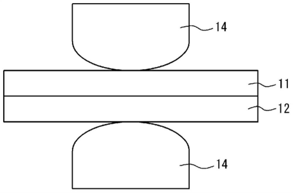
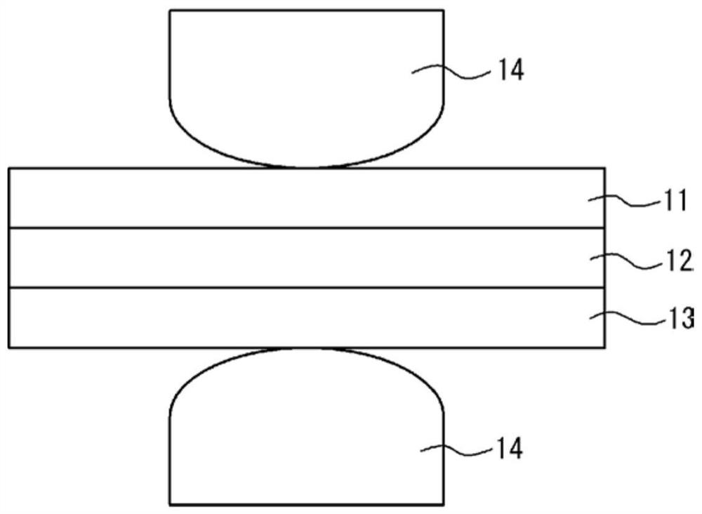
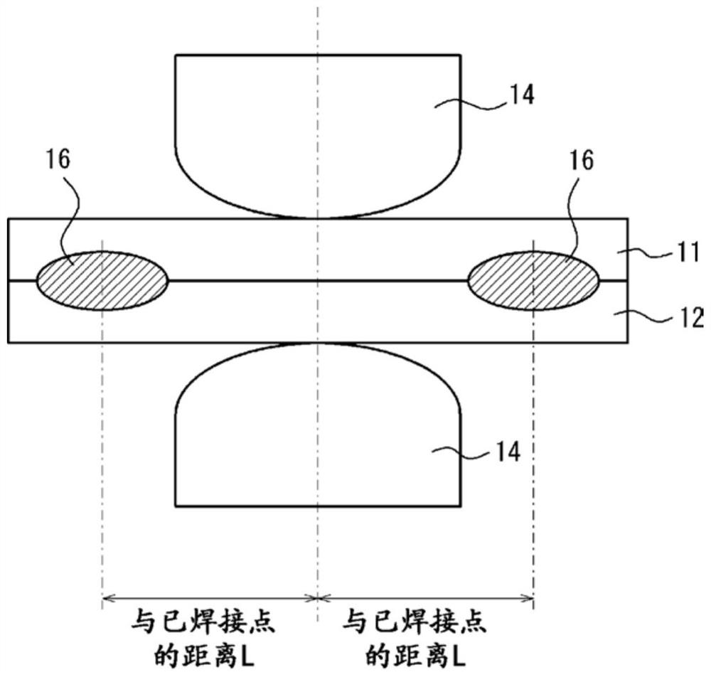
[0146] Here, trial welding and formal welding are figure 1 and figure 2 the interference-free state shown, and Figure 3-6 The state of simulated disturbance is shown. In the drawings, reference numerals 11, 12, and 13 are metal plates, 14 is an electrode, 15 is a spacer, and 16 is a welded point. It should be noted that, if image 3 and Figure 4 As shown, two welded points 16 are provided, and the welding position (the center between the electrodes) is adjusted so that the welded points are in the middle (same as the distance L between the welded points). In addition, in Figure 5 and Figure 6 Among them, spacers 15 are inse...


PUM


Abstract

The main welding and the trial welding before the main welding are performed, and the trial welding is performed under two or more welding conditions. In the trial welding, the preliminary energization and the main energization based on constant current control are performed, and the electrode gap at the time of the preliminary energization is stored. The electrical characteristics, and the time-varying curve of the instantaneous calorific value per unit volume at the time of actual energization. The electrical characteristics between the electrodes in the preliminary energization are compared with the electrical characteristics between the electrodes stored in the preliminary energization of the trial welding, and the target value of the main energization in the main welding is set, and then, the main energization is controlled. Adaptive control welding of energized amount.

Description

technical field [0001] The present invention relates to a resistance spot welding method that can stably secure a nugget diameter without causing dispersion even when the influence of disturbances such as shunts and plate gaps is large. Background technique [0002] In general, resistance spot welding, which is one type of lap resistance welding, is used to join laminated steel plates. [0003] This welding method is a method in which two or more stacked steel plates are sandwiched, pressure is applied from above and below by a pair of electrodes, and a high-current welding current is applied between the upper and lower electrodes for a short time to join them. . In addition, in this welding method, spot-shaped welded portions are obtained by utilizing resistance heating generated by flowing a high-current welding current. This point-shaped welded portion is a portion called a nugget, where both steel plates are melted and solidified at the contact portion of the steel pla...

Claims


Application Information

Patent Timeline
Patent Type & Authority Patents(China)
IPC IPC(8): B23K11/11B23K11/24
CPCB23K11/11B23K11/24B23K11/115B23K11/241B23K11/255B23K11/257B23K11/258
Inventor 泽西央海松田广志池田伦正
Owner JFE STEEL CORP
Learn More