
Camera acquisition digital image equipment and filtering method

A digital image and camera technology, applied in image communication, color TV parts, TV system parts, etc., can solve problems such as multi-software, hardware computing resources, image recognition rate reduction, camera halo, etc. Achieve the effects of simple construction steps, reduced algorithm difficulty, and low transformation costs

Inactive Publication Date: 2020-04-10
TIANDI CHANGZHOU AUTOMATION +1
View PDF3 Cites 0 Cited by
  • Summary
  • Abstract
  • Description
  • Claims
  • Application Information

AI Technical Summary

Problems solved by technology

[0003] However, the application of intelligent image recognition in coal mines is not very ideal, the main reason is the interference of underground car lights and miner's lamps on video images
Because the underground environment is dark and dark, miners must carry miner's lamps for lighting, and underground locomotives must also be equipped with lighting lights, which will cause fatal problems for underground video image recognition: 1. The light directly irradiated or indirectly reflected by lighting equipment will affect the camera. The pixel change of the image collected by the camera can cause halo or blindness of the camera in severe cases, resulting in a decrease in image recognition rate or failure of image recognition
2. The irradiation of mobile lighting equipment on other objects will cause the movement or jump of the shadow of the object, which will affect the judgment of intelligent image recognition and greatly reduce the accuracy of image recognition
3. In the existing intelligent image recognition, digital image filtering algorithms are usually used to suppress the above light source interference, such as image algorithms such as bright spot suppression algorithm and local dynamic contrast adjustment. There are many software and hardware computing resources, and the filtering effect of image pollution caused by the above light sources is poor, which may easily lead to false positives or missed detections of intelligent video

Method used


Image

  • Camera acquisition digital image equipment and filtering method
  • Camera acquisition digital image equipment and filtering method
  • Camera acquisition digital image equipment and filtering method

Examples


Embodiment Construction

[0021] Exemplary embodiments of the present disclosure will be described in more detail below with reference to the accompanying drawings. Although exemplary embodiments of the present disclosure are shown in the drawings, it should be understood that the present disclosure may be embodied in various forms and should not be limited by the embodiments set forth herein. Rather, these embodiments are provided for more thorough understanding of the present disclosure and to fully convey the scope of the present disclosure to those skilled in the art. Therefore, the following description should be understood as an expansion of the thinking of those skilled in the art, rather than as a limitation of the present invention.

[0022] All features of an actual embodiment are described for clarity. In the following description, well-known functions and constructions are not described in detail since they would obscure the invention with unnecessary detail. It should be appreciated that...


PUM


Abstract

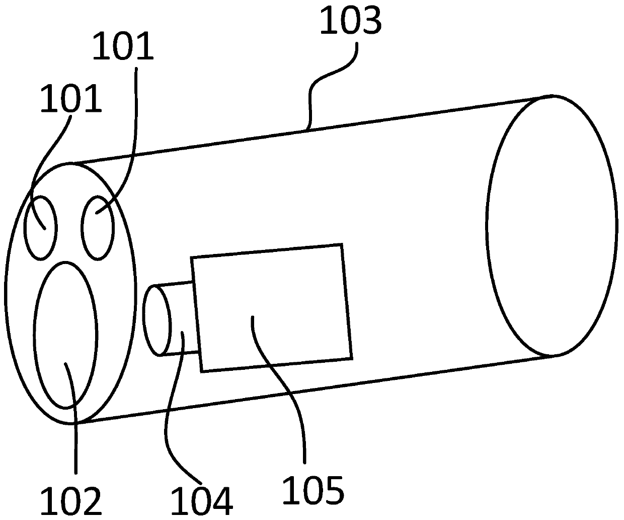
The invention provides camera acquisition digital image equipment and a filtering method. The camera acquisition digital image equipment comprises an infrared light illumination module, a visible light filtering lens and a video acquisition module, wherein the video acquisition module comprises a camera core and a camera shell, and the camera core comprises a lens. According to the camera acquisition digital image equipment and the filtering method, direct interference of a mining head lamp and a car lamp on video images can be directly restrained from the source, and blinding caused by lamplight of the camera is avoided; besides, shadow interference or jump generated when the visible light irradiates the object can be filtered, the algorithm difficulty of intelligent image recognition isreduced, the accuracy of the algorithm is improved, and the camera acquisition digital image equipment provided by the invention is suitable for a transformation scheme of an original universal camera, and is low in transformation cost and simple in construction step.

Description

technical field [0001] The invention relates to the field of video monitoring, in particular to a digital image device collected by a camera and a filtering method. Background technique [0002] With the popularization of underground video surveillance, the application of intelligent image recognition in coal mines is becoming more and more extensive. The intelligent image recognition technology uses the digital images collected by the mine camera, and performs calculation and analysis through the intelligent algorithm embedded in the camera or the back-end server algorithm to realize the perception of the video content, and then judge and identify the corresponding target or not according to the set rules. Make corresponding alarms. Due to the advantages of non-contact detection, wide detection range and low detection cost, intelligent video recognition can better solve the detection requirements of a series of dangerous places such as personnel violations and personnel cr...

Claims


Application Information

Patent Timeline
Patent Type & Authority Applications(China)
IPC IPC(8): H04N7/18H04N5/33
CPCH04N5/33H04N7/18
Inventor 刘冬武福生蒋泽赵小兵姚超修陈辉朱晓洁张明杰陈佩佩
Owner TIANDI CHANGZHOU AUTOMATION
Learn More