
Medical image case comparison device

A medical imaging and contrast device technology, applied in optics, optical components, instruments, etc., can solve the problems of heavy workload, inconvenience, affecting film quality, etc., and achieve the effect of ingenious structure, novel concept, and avoidance of damage

Active Publication Date: 2020-04-10
HENAN PROVINCE HOSPITAL OF TCM THE SECOND AFFILIATED HOSPITAL OF HENAN UNIV OF TCM
View PDF9 Cites 0 Cited by
  • Summary
  • Abstract
  • Description
  • Claims
  • Application Information

AI Technical Summary

Problems solved by technology

[0002] In the existing medical treatment examination, radiation detection is often needed. During the radiation detection, the image film will be printed out for pathological records and to facilitate later research and observation. In addition, pathological images in different treatment periods need to be frequently compared to judge the condition When doctors observe the video film, they always lift the film and point the film at the light source for observation. It is very inconvenient to use this method at this time because it is necessary to repeatedly observe the film of different periods during comparative observation. At the same time, every observation needs to be lifted again to find the best observation angle, which not only has a large workload, but also is very inconvenient for doctors to record while observing and comparing. In addition, frequent lifting of the film by hand will affect the quality of the film, and it will take a long time. Observation effect will be affected after time

Method used


Image

  • Medical image case comparison device
  • Medical image case comparison device
  • Medical image case comparison device

Examples


Embodiment Construction

[0019] The present invention will be further described in detail below in conjunction with the accompanying drawings and embodiments.

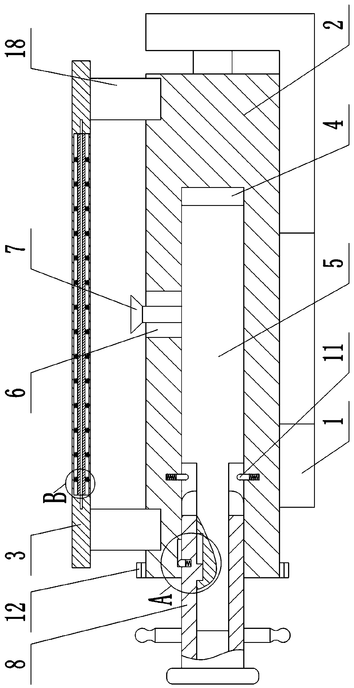
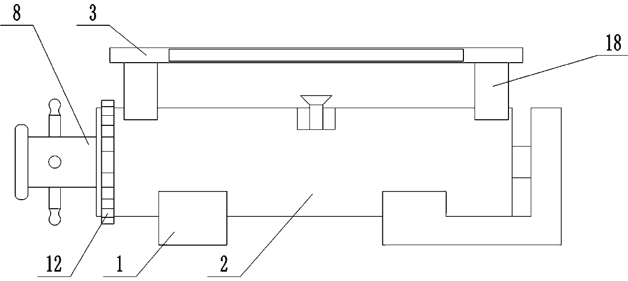
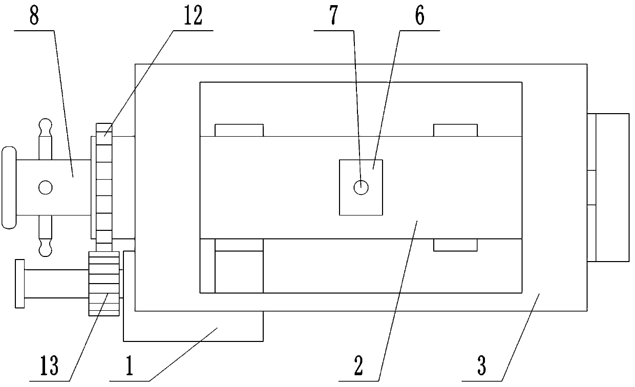
[0020] attached by Figure 1-7 It can be seen that the present invention includes a base 1, a rotatable main shaft 2 is arranged on the top of the base 1, and a plate clamp 3 is fixed on the outer edge of the main shaft 2, and a through hole 4 with an opening at the left end is provided in the center of the main shaft 2, and the through hole 4 is interspersed with There is a rotatable pin shaft 5, the left end of the pin shaft 5 is placed outside the main shaft 2, and the side wall of the main shaft 2 is provided with an arc-shaped groove 6, and the bottom of the arc-shaped groove 6 reaches the surface of the pin shaft 5, and the pin shaft 5 An observation light 7 placed in an arc-shaped groove 6 is fixed on the outer edge of the shaft 5, and a sliding sleeve 8 is set on the left outer edge of the pin shaft 5, and the outer wall of the sliding...


PUM

PropertyMeasurementUnit
Lengthaaaaaaaaaa

Abstract

The invention relates to a medical image case comparison device, which can effectively avoid the problem that a best observation position cannot be fixed due to inconvenience of an existing observation mode and also can effectively avoid the damage of existing traditional observation mode to the film. According to the technical scheme, the device comprises a base, a main shaft is arranged above the base, a flat clamp is fixed on the outer edge surface of the main shaft, a through hole is formed at the center of the main shaft, a pin shaft is inserted into the through hole, an arc-shaped grooveis formed in the main shaft, an observation lamp is fixed on the outer edge surface of the pin shaft, the outer edge on the left side of the pin shaft is sleeved with a sliding sleeve which is slidably connected to the pin shaft through a flat key and a sliding groove, a plurality of clamping grooves evenly distributed in the circumference are formed at the right end of the sliding sleeve, clamping pins arranged on the right side of the sliding sleeve are arranged on the side wall of the through hole, the clamping pins are arranged on the same circumference of the side wall of the through hole and evenly distributed in the circumference, and when the sliding sleeve slides to the rightmost side along the pin shaft, the clamping pins can be clamped into the clamping grooves in the sliding sleeve, and when the sliding sleeve slides to the left, the clamping pins can break away from the clamping grooves. The device is novel in conception and ingenious in structure.

Description

technical field [0001] The invention relates to the technical field of image observation and comparison, in particular to a medical image case comparison device. Background technique [0002] In the existing medical treatment examination, radiation detection is often needed. During the radiation detection, the image film will be printed out for pathological records and to facilitate later research and observation. In addition, pathological images in different treatment periods need to be frequently compared to judge the condition Now when doctors observe the video film, they always lift the film and point the film to the light source for observation. Because of the comparison observation, it is necessary to repeatedly observe the film of different periods. At this time, it is very inconvenient to use this method. At the same time, every observation needs to be lifted again to find the best observation angle, which not only has a large workload, but also is very inconvenient ...

Claims


Application Information

Patent Timeline
IPC IPC(8): G02B27/02
CPCG02B27/024G02B27/028
Inventor 张瑾宁
Owner HENAN PROVINCE HOSPITAL OF TCM THE SECOND AFFILIATED HOSPITAL OF HENAN UNIV OF TCM
Learn More