A high-energy laser fiber bundle and its manufacturing method

A technology of high-energy laser and optical fiber bundle, which is applied in the direction of optical fiber bundle, coupling of optical waveguide, fiber mechanical structure, etc., can solve problems such as temperature rise of optical fiber bundle, achieve the effect of reducing stress, reducing optical fiber transmission loss, and easy to clean dust

Active Publication Date: 2020-12-22
HARBIN ENG UNIV
View PDF9 Cites 0 Cited by
  • Summary
  • Abstract
  • Description
  • Claims
  • Application Information

AI Technical Summary

Problems solved by technology

[0004] In order to overcome the deficiencies in the existing fiber bundles, the purpose of the present invention is to provide a high-energy laser fiber bundle, which can solve the defects in the above-mentioned fiber bundles
Under the premise of ensuring that the relative fixed position of the optical fiber does not change, solve the problem of temperature rise caused by the accumulation of dust on the end face of the fiber bundle, and the transmission loss problem caused by the mutual stress between the fibers, and increase the laser power transmitted by the fiber bundle

Method used


Image

  • A high-energy laser fiber bundle and its manufacturing method
  • A high-energy laser fiber bundle and its manufacturing method
  • A high-energy laser fiber bundle and its manufacturing method

Examples


Embodiment Construction

[0025] The present invention will be further described below in conjunction with the accompanying drawings.

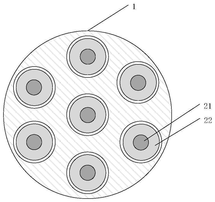
[0026] In the figure: 1—microporous glass plate; 2—transmission optical fiber, 21—fiber core, 22—fiber cladding, 23—fiber coating; 3—optical fiber bundle protective layer; 4—thermal silicone grease; 5—ultraviolet Curing glue sealing surface; 6-laser.

[0027] The invention relates to the technical field of fiber lasers and provides a high-energy laser fiber bundle. The optical fiber bundle includes three parts: optical fiber, packaging structure, and end face fixing structure. An optical fiber consists of a core, cladding and transparent coating. The encapsulation structure includes a non-cured heat-conducting medium filled inside the fiber bundle and a protective layer of the fiber bundle, wherein the heat-conducting medium has the function of reducing the stress between the optical fibers and reducing the transmission loss of the optical fiber. At the same time, t...


PUM


Abstract

The invention, which belongs to the technical field of optical fibers, particularly relates to a high-energy laser optical fiber bundle and a manufacturing method thereof. The high-energy laser optical fiber bundle is composed of optical fibers, a packaging structure and an end face fixing structure. Each optical fiber is formed by tightly attaching a fiber core, a wrapping layer and a transparentcoating layer from inside to outside. The packaging structure comprises two parts of heat conduction silicone grease and an optical fiber bundle protection layer, the heat conduction silicone greaseuniformly fills gaps of multiple optical fibers, and the optical fiber bundle protection layer wraps the outside of the heat conduction silicone grease. The end face fixing structure comprises an ultraviolet curing adhesive packaging surface arranged at the input end of the optical fiber bundle and a microporous glass plate arranged at the output end of the optical fiber bundle. The heat conduction silicone grease filling the optical fiber bundle can reduce the stress effect on the optical fibers to reduce the transmission loss of the optical fibers. In addition, the heat conduction silicone grease and the optical fiber bundle protective layer serve as heat-conducting structures to dissipate heat of the optical fiber bundle. And the microporous glass plate arranged at the output end solvesthe problem of positioning failure of the ultraviolet curing adhesive at a high temperature, and optical fiber positioning is performed at the high temperature.

Description

technical field [0001] The invention belongs to the technical field of optical fibers, and in particular relates to a high-energy laser optical fiber bundle and a manufacturing method thereof. Background technique [0002] Fiber laser is a new type of laser with good beam quality, high stability and high efficiency. As a representative of the third-generation laser technology, it has been widely used in industry, medical treatment, national defense and other fields. With the development of application technology, the output power requirements of fiber lasers are getting higher and higher. The fiber bundle is an important part of the fiber laser, and its performance affects the power index of the fiber laser. At present, the existing optical fiber bundles perform poorly in terms of heat dissipation and dust-proof performance on the end face, resulting in the fiber bundle being heated and burned due to dust accumulation and light leakage. In this way, for the safety performan...

Claims


Application Information

Patent Timeline
Patent Type & Authority Patents(China)
IPC IPC(8): G02B6/06G02B6/44G02B6/25
CPCG02B6/06G02B6/25G02B6/44
Inventor 孙伟民耿涛陈龙震闫奇陈旭东金夕人张英华朱清柱王安之王佳斌
Owner HARBIN ENG UNIV
Why Eureka
Try Eureka