
Method and device for improving micro-deformation loading accuracy

A loading device and micro-deformation technology, which is applied in the direction of measuring device, using repeated force/pulsation force to test the strength and strength characteristics of materials, etc., can solve the problem of reducing the uncertainty of micro-deformation loading device and large uncertainty of micro-deformation loading, etc. problem, to achieve the effect of uniform deformation loading in the whole field, high accuracy of repeated loading, and elimination of thread gap

Active Publication Date: 2021-08-10
SHANGHAI JIAO TONG UNIV
View PDF17 Cites 0 Cited by
  • Summary
  • Abstract
  • Description
  • Claims
  • Application Information

AI Technical Summary

Problems solved by technology

[0003] Aiming at the shortcomings of the existing micro-deformation loading uncertainty, the present invention proposes a method and device for improving the micro-deformation loading accuracy, reducing the deformation hysteresis caused by the internal stress of the elastic deformation area of ​​the test piece and reducing the driving device and the test device. The method and device for the displacement error caused by the connection contact force deformation or the connection gap between parts can greatly reduce the uncertainty of the micro-deformation loading device, making it applicable to the field of deformation measurement and calibration requiring high precision

Method used


Image

  • Method and device for improving micro-deformation loading accuracy
  • Method and device for improving micro-deformation loading accuracy
  • Method and device for improving micro-deformation loading accuracy

Examples


Embodiment Construction

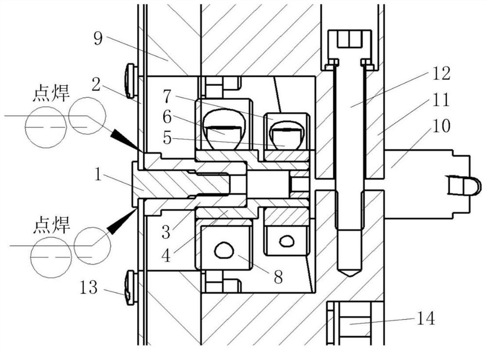
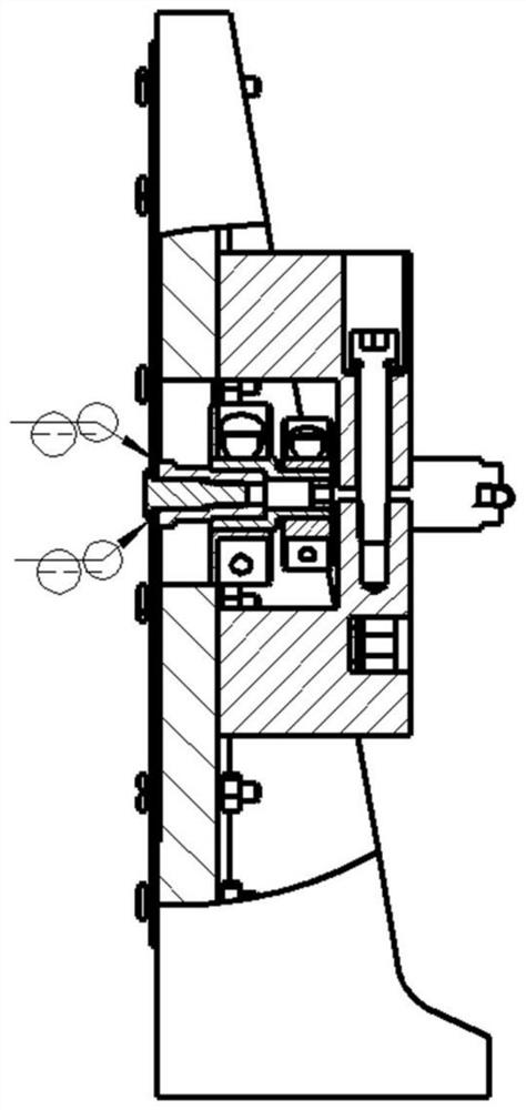
[0024] Such as figure 1 As shown, this embodiment relates to a device for improving the accuracy of micro-deformation loading, including: a test piece assembly composed of a fastening screw test piece 1, a thin-walled disc part test piece 2, a fastening screw sleeve test piece 3, and a coupling And the piezoelectric actuator 10, wherein: the test piece assembly and the driving end of the piezoelectric actuator 10 are connected by a rigid coupling, the test piece assembly is fixedly arranged on the base, and the piezoelectric actuator 10 is fixedly arranged on the actuator On the base 11 of the test piece, when the piezoelectric actuator 10 produces a specified displacement and drives the rigid coupling to drive the central area of ​​the test piece assembly to produce a same displacement.

[0025] Between the fastening screw test piece 1 and the thin-walled disc part test piece 2 and between the thin-walled disc part test piece 2 and the fastening screw sleeve test piece 3, all...


PUM


Abstract

A method for improving the accuracy of a micro-deformation loading device. The test piece made of constant elastic alloy material is divided into a central displacement region, a middle ring elastic deformation region and an outer peripheral fastening region, and the test piece is designed and assembled separately to form a test piece assembly to eliminate processing. The deformation caused by the disc-shaped thin-walled area of ​​the test piece and the influence of the deformation of the cutting residual stress deformation area generated during the machining process are determined by the connection between the outer circle of the output interface of the radial clamping drive device and the outer circle of the cylindrical projecting end of the specimen. Reduce the displacement error caused by the threaded connection gap or contact force deformation at the connection between the high-precision drive device and the specimen. The method and device of the present invention reduce the deformation hysteresis caused by the internal stress after the deformation of the elastic deformation area of ​​the test piece, and reduce the displacement error caused by the contact force deformation or the connection gap between the driving device and the test piece, so that the micro-deformation loading device can be uncertain. greatly reduced.

Description

technical field [0001] The invention relates to a technology in the field of deformation measurement, in particular to a method and a device for improving the accuracy of micro-deformation loading. Background technique [0002] The current deformation measurement technology mainly traces the source through the wavelength, and theoretically analyzes the influencing factors of the environment, so as to evaluate the uncertainty of the measurement system. Obviously, this method lacks experimental verification and calibration. The existing high-precision micro-deformation loading device is realized by micro-deformation loading, and micro-deformation loading is applied to the deformation process of the object, which involves two processes of micro-deformation transmission and object deformation. The precision requirement from nm to tens of nm, the transfer process of micro-deformation is easily affected by the micro-gap of the connection (such as thread gap), which makes the trans...

Claims


Application Information

Patent Timeline
Patent Type & Authority Patents(China)
IPC IPC(8): G01N3/32G01N3/04G01B21/32G01N1/28G01N1/44
CPCG01B21/32G01N1/286G01N1/44G01N3/04G01N3/32G01N2001/2873
Inventor 蔡萍刘持越隆军
Owner SHANGHAI JIAO TONG UNIV
Learn More