Combined oil damper stress performance testing device

An oil damper and testing device technology, applied in measuring devices, instruments, scientific instruments, etc., can solve the problems of limited seismic performance of a single oil damper and lack of mechanical performance of a combined oil damper, so as to ensure the safety of the test process. Effect

Inactive Publication Date: 2020-04-10
HARBIN INST OF TECH
View PDF4 Cites 0 Cited by
  • Summary
  • Abstract
  • Description
  • Claims
  • Application Information

AI Technical Summary

Problems solved by technology

[0004] Previous experimental studies only tested the tensile, compressive and impact resistance properties of a single oil damper, but the seismic performance of a single oil damper is limited. In order to achieve a better seismic effect, oil dampers can be used in combination. A testing device for the mechanical performance of a combined oil damper

Method used


Image

  • Combined oil damper stress performance testing device
  • Combined oil damper stress performance testing device
  • Combined oil damper stress performance testing device

Examples


specific Embodiment approach 1

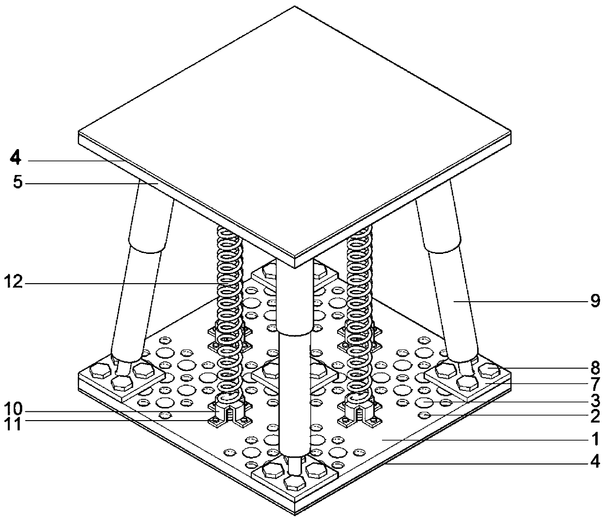
[0014] Specific implementation mode one: as Figure 1 ~ Figure 4 As shown, the present invention discloses a combined oil damper force performance testing device, including a bottom plate 1, a top plate 5, two anti-skid layers 4, four springs 12 and five oil dampers 9; the bottom plate 1 and The top plate 5 is a cuboid plate, the bottom of the bottom plate 1 and the top of the top plate 5 are provided with an anti-skid layer 4, the bottom plate 1 and the top plate 5 are elastically connected by four springs 12 and five oil dampers 9, and the five oil dampers 9 are arranged in the middle and four corners of the bottom plate 1 and the top plate 5 respectively, and the four springs 12 are arranged in a rectangular shape and alternately arranged with the four oil dampers 9 arranged in the corners.

specific Embodiment approach 2

[0015] Embodiment 2: This embodiment is a further description of Embodiment 1. Both the bottom plate 1 and the top plate 5 are steel plates.

specific Embodiment approach 3

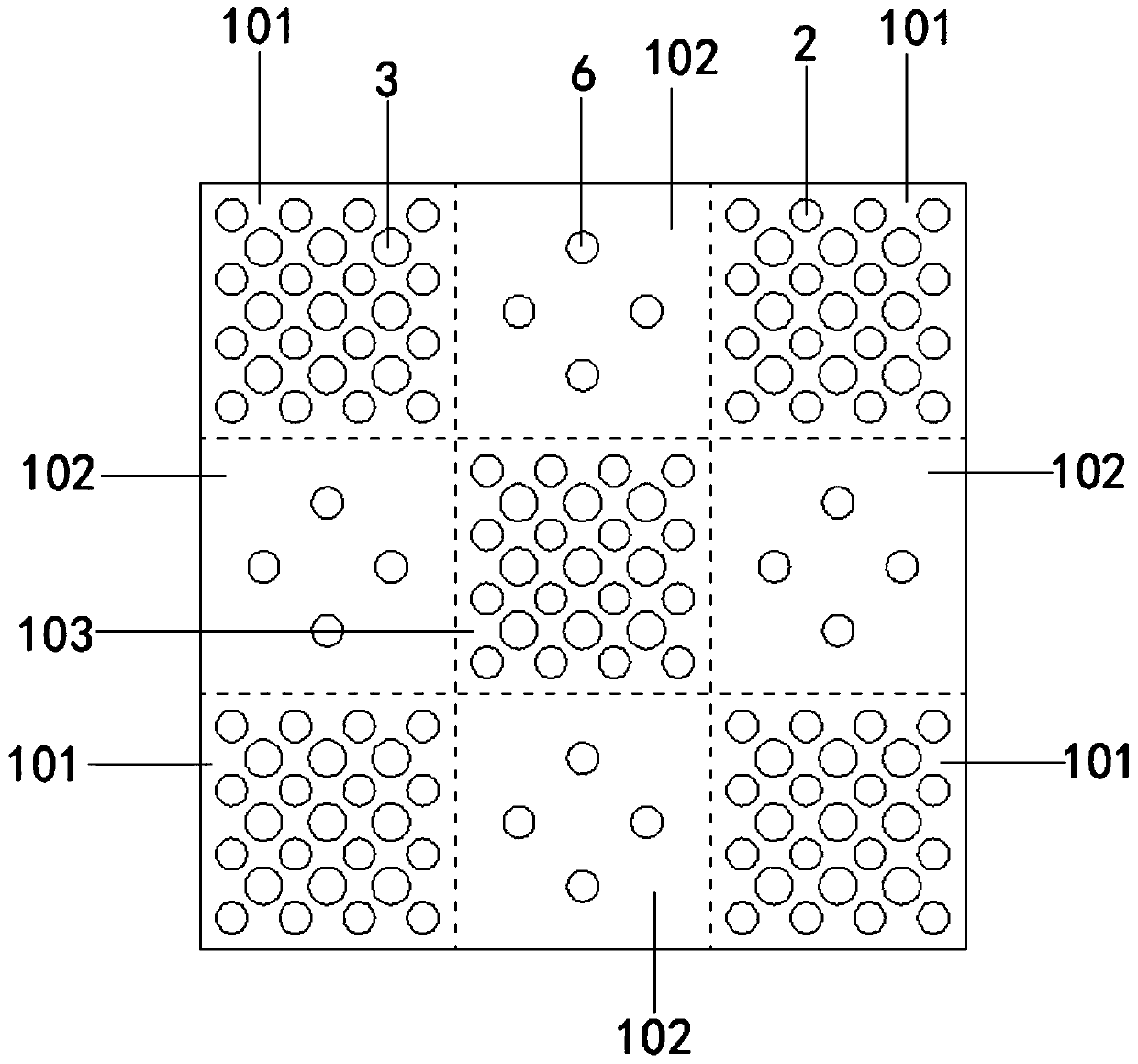
[0016] Specific implementation mode three: as figure 1 , 2 As shown, this embodiment is a further description of Embodiment 2. The opposite surfaces of the bottom plate 1 and the top plate 5 are equally divided into nine areas, and the nine areas include the middle area 103, the four corner areas 101 and Four side regions 102, the middle region 103 and the four corner regions 101 are all provided with a plurality of (nine) hemispherical grooves 3 and a plurality of (sixteen) base bolt holes 2, and the plurality (nine) 1) hemispherical grooves 3 and multiple (sixteen) base bolt holes 2 are arranged in a rectangular array and multiple (nine) hemispherical grooves 3 and multiple (sixteen) base bolt holes 2 one by one Arranged alternately, multiple (four) spring bolt holes 6 are provided in the middle of each of the four side regions 102 .


PUM


Abstract

The invention discloses a combined oil damper stress performance testing device, and belongs to the technical field of building anti-seismic device performance testing. Anti-skid layers are arranged at the bottom of a bottom plate and the top of a top plate respectively, the bottom plate and the top plate are elastically connected through four springs and five oil dampers, the five oil dampers arerespectively arranged at the middles and the four corners of the bottom plate and the top plate, the four springs are arranged in a rectangular shape, and the four springs and the four oil dampers arranged at the corners are arranged alternately. The bottom plate and the top plate can be used for carrying out multi-angle arrangement on the oil dampers, and the springs can be used for applying tension pseudo stress and pressure pseudo stress to the oil dampers, so that the comprehensive stress performance test research of the multiple oil dampers under different combinations and different stress conditions can be carried out. The anti-skid materials arranged on the lower surface of the bottom plate and the upper surface of the top plate can effectively resist horizontal friction force between the device and a test instrument, so that a rigorous test process and a precise test result are guaranteed.

Description

technical field [0001] The invention relates to a device for testing the mechanical performance of a combined oil damper, which belongs to the technical field of performance testing of building anti-seismic devices. Background technique [0002] Considering the special seismic environment in which the port engineering structure is located, and its complex deformation and serious damage under the earthquake, it is urgent to carry out research on seismic isolation of port engineering structures. [0003] At present, port engineering mainly adopts various combinations of shock-absorbing and isolating bearings in the pile foundation structure, such as rubber and spring-absorbing and isolating bearings, magneto-rheological and shock-isolating bearings, etc. In recent years, different forms of dampers (spring dampers, pulse dampers, wind dampers, and hydraulic dampers represented by oil dampers and hydraulic viscous dampers) have begun to be used because of their good energy absor...

Claims


Application Information

Patent Timeline
Patent Type & Authority Applications(China)
IPC IPC(8): G01N3/00
CPCG01N3/00G01N2203/0017G01N2203/0019
Inventor 唐亮张征李雪伟凌贤长满孝峰张毅刘书幸
Owner HARBIN INST OF TECH
Why Eureka
Try Eureka