Natural gas engine and EGR second-stage cooling device thereof

An EGR cooler and two-stage cooling technology, which is applied to engine components, combustion engines, machines/engines, etc., can solve problems such as prone to knocking, low temperature after cooling, and affecting engine life, so as to improve reliability and reduce The demand for heat dissipation power and the effect of solving difficult matching

Inactive Publication Date: 2020-04-10
WEICHAI POWER CO LTD
View PDF6 Cites 3 Cited by
  • Summary
  • Abstract
  • Description
  • Claims
  • Application Information

AI Technical Summary

Problems solved by technology

[0002] In high-temperature areas, the ambient temperature can reach more than 40 degrees Celsius. When a natural gas engine (LNG engine) operates at high load in a high-temperature environment, due to the high ambient temperature, the heat dissipation power of the intercooler decreases, and the intake air temperature after the intercooler is high. When the engine water temperature is high, the temperature of the EGR exhaust gas after cooling is also relatively high. After the intercooled air is mixed with the EGR exhaust gas, the temperature will rise further, and knocking will easily occur, which will affect the life of the engine.
The EGR exhaust gas of a high-power natural gas engine has a high temperature and a large flow rate, but the required cooling temperature is low. This part of the heat needs to be absorbed by the coolant and dissipated into the air through the radiator and fan of the water tank. The high ambient temperature reduces the heat dissipation of the water tank. The heat dissipation power of the radiator requires a larger radiator and fan to dissipate the heat and achieve the thermal balance of the vehicle. However, due to the layout space of the vehicle, it is difficult to match a large enough intercooler and fan

Method used


Image

  • Natural gas engine and EGR second-stage cooling device thereof
  • Natural gas engine and EGR second-stage cooling device thereof

Examples


Embodiment Construction

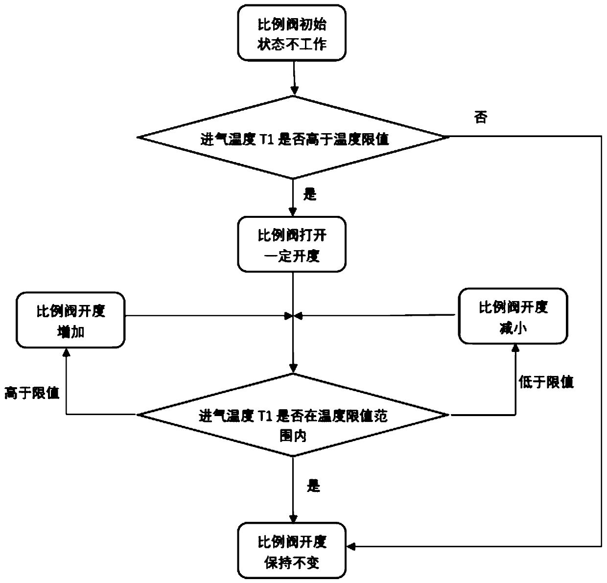
[0025] In view of this, the core of the present invention is to disclose an EGR secondary cooling device for a natural gas engine, so as to ensure the service life of the engine. In addition, another core of the present invention is to disclose a natural gas engine with the above-mentioned EGR secondary cooling device.

[0026] In order to enable those skilled in the art to better understand the solution of the present invention, the present invention will be further described in detail below in conjunction with the accompanying drawings and specific embodiments.

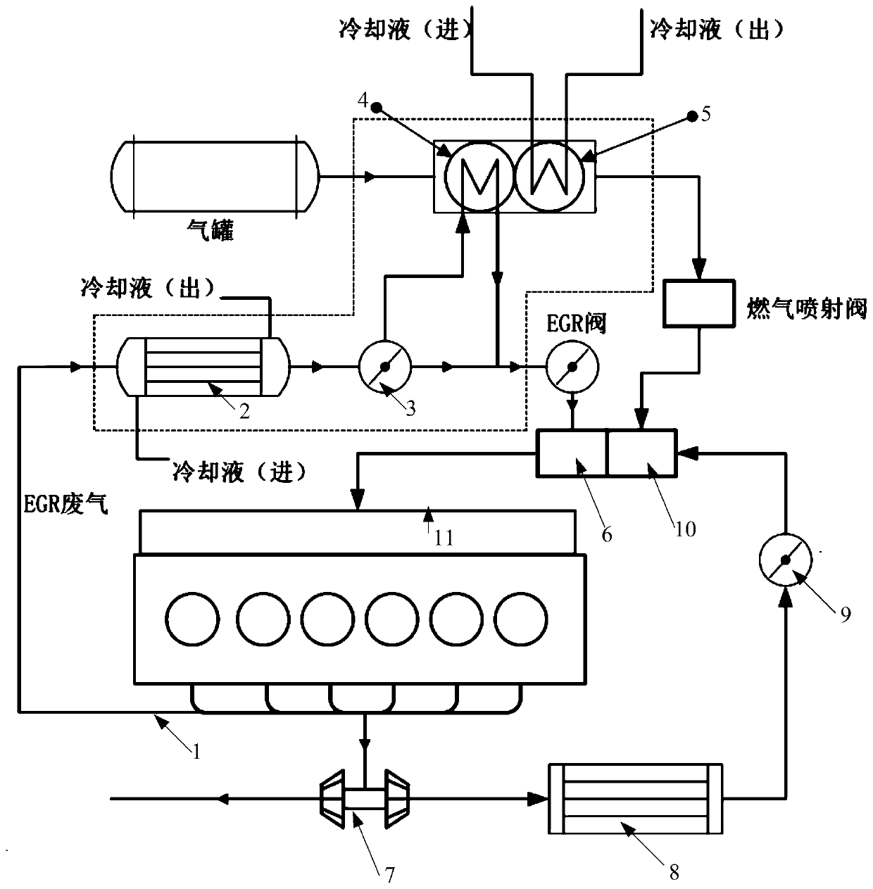
[0027] Such as figure 1 As shown, the present invention discloses an EGR secondary cooling device for a natural gas engine, which is used for secondary cooling of EGR exhaust gas, which includes an EGR cooler 2 and a carburetor. Wherein, the input end of the EGR cooler 2 is connected with the exhaust pipe 1 of the EGR exhaust gas, that is, the EGR exhaust gas is cooled by the EGR cooler 2 at the first stage. The a...


PUM


Abstract

The invention discloses a natural gas engine and an EGR second-stage cooling device thereof for second-stage cooling of EGR waste gas. The natural gas engine comprises an EGR cooler and a vaporizer, wherein an input end of the EGR cooler is connected with an exhaust pipe of the EGR waste gas; the vaporizer comprises a cooling liquid vaporizing part and an EGR waste gas vaporizing part both for heat exchange with LNG; an inlet end of the EGR waste gas vaporizing part is connected with an output end of the EGR cooler; and an outlet end of the EGR waste gas vaporizing part is connected with an EGR mixer. Low-temperature natural gas is used for secondary cooling of the EGR waste gas cooled by the EGR cooler, so that the temperature of the EGR waste gas is lowered, the temperature of mixed gasformed by mixing with air after intercooling is reduced, the knocking problem caused by higher intake temperature is solved, and the reliability of the engine is improved; and as the natural gas can take away a lot of heat, the heat needing to be taken away by the cooling liquid is greatly reduced, the whole vehicle heat dissipation power demand is reduced, and the problem of difficult matching between a whole vehicle radiator and a fan is solved.

Description

technical field [0001] The invention relates to the technical field of power devices, in particular to a natural gas engine and an EGR secondary cooling device thereof. Background technique [0002] In high-temperature areas, the ambient temperature can reach more than 40 degrees Celsius. When a natural gas engine (LNG engine) operates at high load in a high-temperature environment, due to the high ambient temperature, the heat dissipation power of the intercooler decreases, and the intake air temperature after the intercooler is high. When the engine water temperature is high, the temperature of the EGR exhaust gas after cooling is also relatively high. After the intercooled air is mixed with the EGR exhaust gas, the temperature will rise further, and knocking will easily occur, which will affect the life of the engine. The EGR exhaust gas of a high-power natural gas engine has a high temperature and a large flow rate, but the required cooling temperature is low. This part ...

Claims


Application Information

Patent Timeline
Patent Type & Authority Applications(China)
IPC IPC(8): F02M26/24F02M26/25F02M26/28F02M26/30F02M26/32F02M21/06F02G5/04F02M26/33
CPCF02G5/04F02G2260/00F02M21/06F02M26/24F02M26/25F02M26/28F02M26/30F02M26/32F02M26/33Y02T10/12Y02T10/30
Inventor 刘振赵红兵武泽军
Owner WEICHAI POWER CO LTD
Why Eureka
Try Eureka