A zigzag stepped variable section grid rudder structure based on drop zone control

A technology of grid structure and grid rudder, which is applied in space navigation equipment, space navigation vehicles, space vehicle guidance devices, etc., can solve the problem of high-speed re-entry and landing zone control sections that cannot meet the requirements of light weight and high efficiency, and cannot Use attitude control, poor aerodynamic shape and other problems to achieve the effect of shortening the production cycle, keeping the structure intact, and reducing the impact of the carrying capacity

Active Publication Date: 2021-02-09
BEIJING INST OF ASTRONAUTICAL SYST ENG +1
View PDF8 Cites 0 Cited by
  • Summary
  • Abstract
  • Description
  • Claims
  • Application Information

AI Technical Summary

Problems solved by technology

The XX-2F escape fairing adopts a grid-style fixed-wing structure, but it cannot be used for attitude control, it is only used to enhance aerodynamic stability
In the field of small solid rockets, the grid rudder structure has been tried, but the size is small (outside dimension not exceeding 1000mm), the section is fixed (rectangular section with equal wall thickness, the shock wave is not easy to penetrate the grid, and the aerodynamic shape is poor), and the locking The surface is mostly flat (additional structure is required to limit the degree of freedom in the other direction, and the structure is bulky), and it is mostly used for low-speed ascending sections, and cannot be applied to high-speed re-entry landing zone control sections that require light weight and high efficiency.

Method used


Image

  • A zigzag stepped variable section grid rudder structure based on drop zone control
  • A zigzag stepped variable section grid rudder structure based on drop zone control
  • A zigzag stepped variable section grid rudder structure based on drop zone control

Examples


Embodiment Construction

[0025] According to the realization requirements of the overall layout and to meet the requirements of load strength, stiffness, heat protection, etc., conduct preliminary coordination and parameter adjustment through engineering calculations and finite element analysis, ensure manufacturing accessibility through technological research, and carry out strength testing through static tests and functional tests. , functions and other overall requirements for indicator verification.

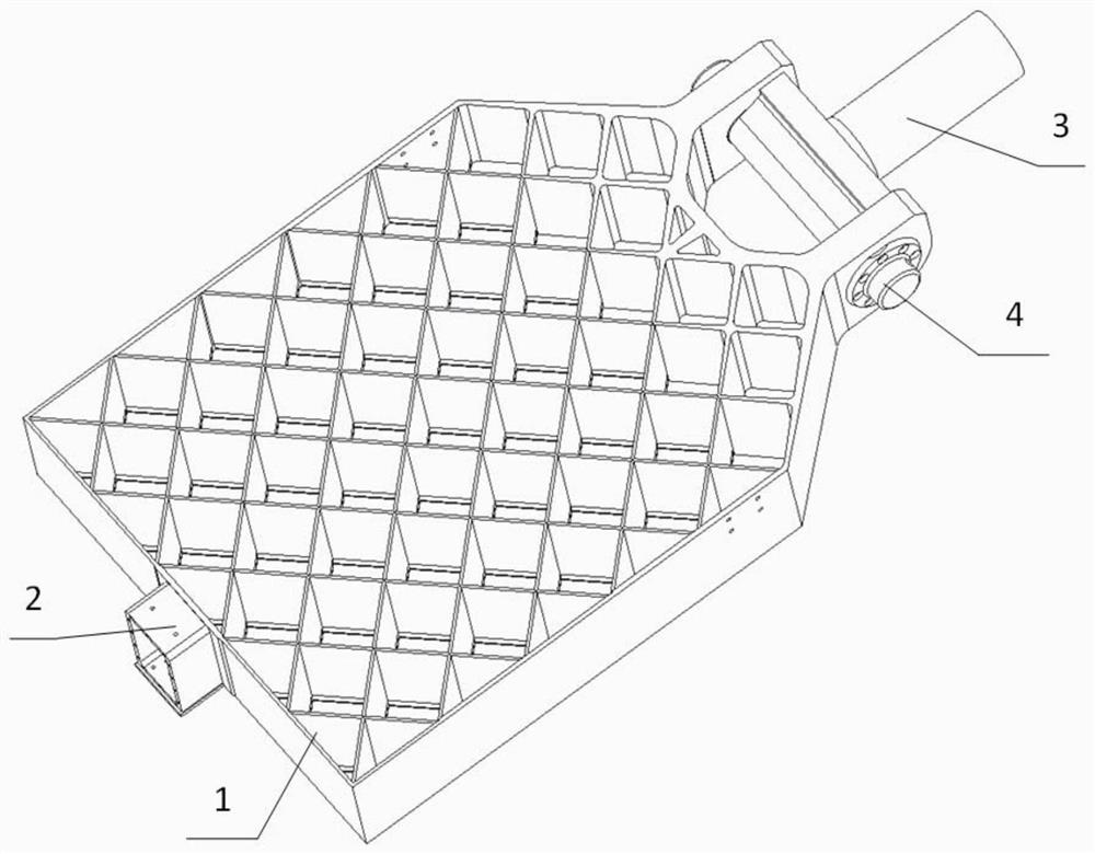
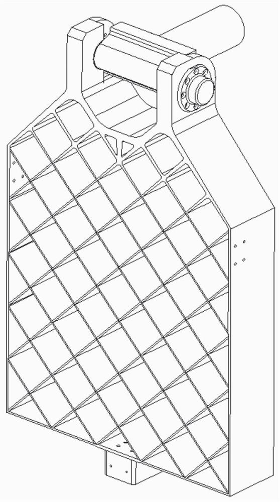
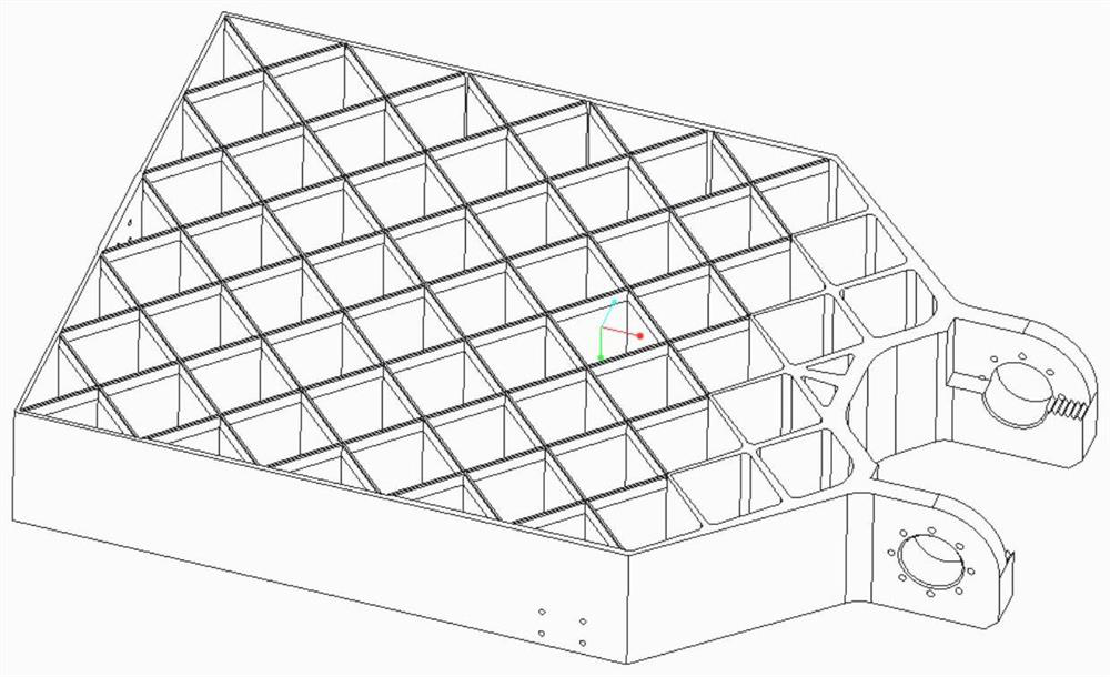
[0026] The present invention provides a sawtooth step-type variable-section grid rudder structure based on landing area control, comprising: a grid rudder body 1 , an explosive bolt box 2 , a special-shaped rotating shaft 3 , and an unfolding shaft 4 .

[0027] One end of the grid rudder body 1 is connected to the special-shaped rotating shaft 3 through the unfolding shaft 4; it is used to rotate around the rotating shaft when reentry and returning. The axis of the special-shaped rotating shaft 3 and...


PUM


Abstract

The invention discloses a sawtooth step type variable-section grid rudder structure based on falling area control, which comprises a grid rudder body, an explosive bolt box, a special-shaped rotatingshaft and an unfolding shaft, wherein one end of the grid rudder body is connected with the special-shaped rotating shaft through the unfolding shaft and used for rotating around the rotating shaft during reentry and return; the axis of the special-shaped rotating shaft is perpendicular to the axis of the unfolding shaft; and the other end of the grid rudder body is connected with the explosive bolt box through a high-temperature alloy bolt and used for being connected with the rocket wall when a carrier rocket flies in an ascending stage. The surface of the grid rudder body is divided into aplurality of evenly-distributed grid structures, the cross section of the side wall of each grid structure is a sharp-end blunt-tail-shaped cross section and used for efficiently providing posture control force during return, and the thickness change trend of the wall surface of each grid structure is the same. The grid rudder structure can be suitable for a high-speed reentry falling area controlsection with light weight and high efficiency requirements, and fills the blank in the field of sublevel reentry falling area control of carrier rockets in China.

Description

technical field [0001] The invention relates to a sawtooth step-shaped variable-section grid rudder structure based on landing area control, in particular to a stepped sawtooth-shaped grid rudder structure with integrated force transmission and locking and a grid section with pointed head and blunt tail with variable section, which is suitable for The field of launch vehicle sub-stage landing area control that requires efficient aerodynamic control. Background technique [0002] At present, my country's Long March series of launch vehicles maintain a high-strength and high-density launch state, and the sub-stage wreckage landing area and safety have become key factors affecting the flight plan and delivery performance of the launch vehicle. In order to improve the safety of the wreckage landing area of ​​the launch vehicle sub-stage and improve the adaptability of the rocket mission, it is proposed to use the grid-style rudder surface structure to control the landing area. ...

Claims


Application Information

Patent Timeline
Patent Type & Authority Patents(China)
IPC IPC(8): B64G1/22B64G1/24
CPCB64G1/22B64G1/24
Inventor 闫伟王辰李泽琛王淑范张希张晓晖曹昱张东王婕尹莲花李志伟任东鸿
Owner BEIJING INST OF ASTRONAUTICAL SYST ENG
Why Eureka
Try Eureka