
Transparent powder barrel device applied to additive manufacturing

An additive manufacturing and transparent powder technology, applied in the field of additive manufacturing, can solve the problems of empty burning of equipment, untimely powder addition, and reduced product quality, reducing thread screwing time, improving fastening tightness, reducing The effect of installation and removal

Active Publication Date: 2020-04-10
成都青石激光科技有限公司
View PDF3 Cites 0 Cited by
  • Summary
  • Abstract
  • Description
  • Claims
  • Application Information

AI Technical Summary

Problems solved by technology

[0004] (1) The overall weight and volume of the powder bucket device are large, which makes it difficult and troublesome to install and disassemble, replace the powder, and clean the powder bucket;
[0005] (2) The air path of the powder barrel device is placed outside the barrel body or in the inner cavity of the powder barrel. When the air path is placed outside the barrel body, it will affect the appearance of the outside, and if it is placed in the inner cavity of the powder barrel, it will be inconvenient for the powder barrel. internal cleaning;
[0006] (3) The storage part of the powder bucket device is opaque, and the amount of powder is not easy to observe, resulting in the equipment having powder-free printing after the powder is used up, causing damage to the equipment;
[0007] (4) The powder bucket device does not have a low-level reminder of the amount of powder printed, which leads to untimely powder addition, resulting in unfavorable conditions such as empty burning of the equipment;
[0008] (5) The barrel cover is threaded and screwed with the powder barrel. When installing and disassembling, a large force is required to rotate the barrel cover. At the same time, because the connection between them is threaded, friction will Fine dust is produced and falls into the powder bucket during closing and dismounting, polluting the powder in the inner cavity of the powder bucket device and reducing the quality of printed products

Method used


Image

  • Transparent powder barrel device applied to additive manufacturing
  • Transparent powder barrel device applied to additive manufacturing
  • Transparent powder barrel device applied to additive manufacturing

Examples


Embodiment 1

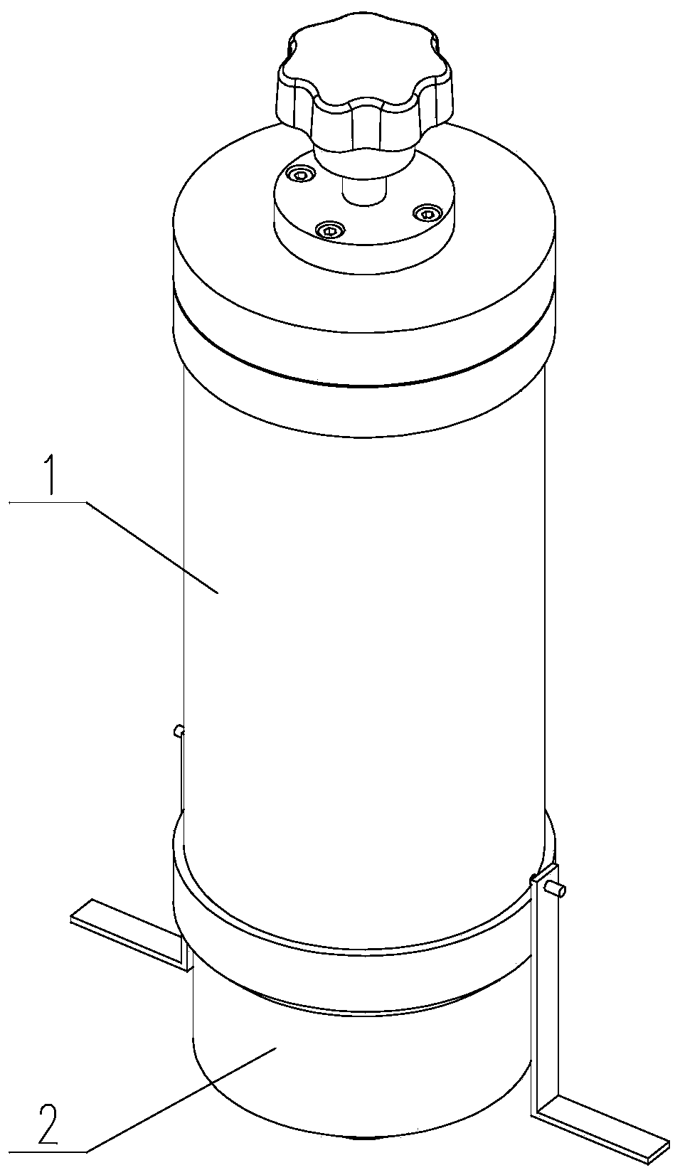
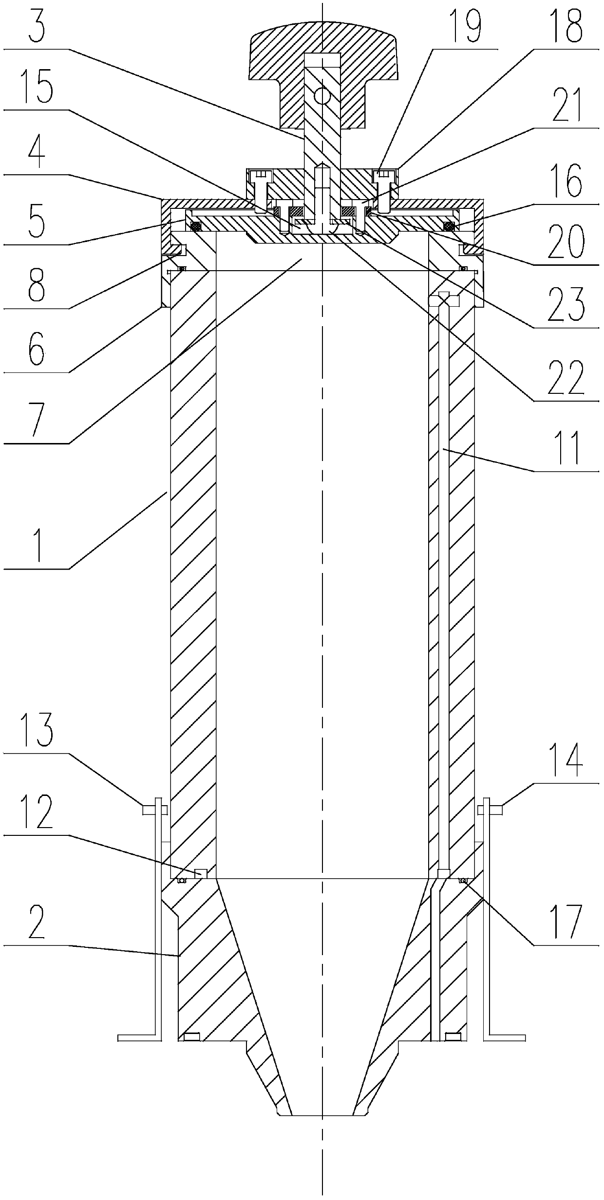
[0052] Such as Figure 2-Figure 10 As shown, the present invention is a transparent powder bucket device applied to additive manufacturing, including a powder bucket body 1 whose axes coincide with each other, and an upper powder seat assembly and a lower powder seat respectively installed at the upper and lower ends of the powder barrel body 1 2. The powder upper seat assembly includes a screw cap 4, a pressing block 5 and a powder upper seat 6. The powder upper seat 6 is connected to the upper end of the powder barrel body 1, and a through hole 7 for powder upper is provided on it. The screw cap 4 is located above the powder upper seat 6, and is clamped with the powder upper seat 6. When the screw cap 4 and the powder upper seat 6 are interlocked in the axial direction, the pressure block 5 is located between the screw cap 4 and the upper powder seat 6. Between the powder seats 6, the briquetting block 5 covers the through hole 7, and a pusher 3 for increasing the distance b...

Embodiment 2

[0057] This embodiment is based on the embodiment 1, and makes a specific implementation description of the clamping structure between the screw cap 4 and the powder upper seat 6 .

[0058] Such as Figure 3-Figure 7 As shown, on the inner wall of the screw cap 4 near the opening of the screw cap, along the circumferential direction of the screw cap 4, a plurality of arc-shaped strips A8 are evenly arranged in sequence, and the arc-shaped strips A8 are all along the The circumference extension of screw cap 4, such as Figure 6 shown;

[0059] On the upper end of the outer wall of the upper powder seat 6, along the circumferential direction of the upper powder seat 6, a plurality of arc-shaped bars B9 are evenly arranged in sequence, and the arc-shaped bars B9 extend along the circumference of the powder upper seat 6. ,Such as Figure 7 shown;

[0060] The upper end of the powder-feeding seat 6 is inserted into the screw cap 4, and the screw cap 4 can be rotated so that the...

Embodiment 3

[0064] This embodiment is an implementation description about the gas path setting of the present invention.

[0065] The inside of the powder bucket body 1 is provided with an air intake passage 11 for constant pressure ventilation, and the air intake passage 11 extends along the axial direction of the powder bucket body 1, and its top end is in contact with the inside of the powder bucket body 1. The cavity is connected, and its bottom extends downwards and runs through the lower powder seat 2.

[0066] The airtight cavity of the powder bucket device of the present invention communicates with the outside world through the air-ventilating channel 11 to keep the internal pressure constant.

[0067] Since the air intake passage is arranged inside the barrel body 1, when the ratio of the length dimension of the air intake passage 11 to the cross section is not large, it is preferable to process the air intake passage 11 inside the powder barrel barrel 1 by drilling; When the ra...


PUM

PropertyMeasurementUnit
densityaaaaaaaaaa
densityaaaaaaaaaa

Abstract

The invention discloses a transparent powder barrel device applied to additive manufacturing. The device comprises a powder barrel body, a powder feeding base assembly and a powder discharging base, wherein the powder feeding base assembly and the powder discharging base are installed at the upper end and the lower end of the powder barrel body respectively, the powder feeding base assembly comprises a screwing cover, a pressing block and a powder feeding base, the powder feeding base is connected with the upper end of the powder barrel body and provided with a through hole used for feeding powder, the screwing cover is located at the upper portion of the powder feeding base and connected with the powder feeding base in a clamped mode, the screwing cover and the powder feeding base are interlocked in the axial direction when the screwing cover is connected with the powder feeding base in a clamped mode, the pressing block is located between the screwing cover and the powder feeding base and covers the through hole, a pushing piece used for increasing the distance between the screwing cover and the pressing block is installed at the upper portion of the screwing cover, and the pushing end of the pushing piece penetrates through the screwing cover and then abuts against or is connected with the pressing block. According to the device, a barrel cover is buckled to shorten the thread screwing time and reduce the contact area of a end cover and the powder feeding base at the same time so as to greatly reduce powder pollution generated by friction during thread screwing, and meanwhile, the powder feeding base does not need to be rotated repeatedly, so that the level of difficulty of mounting and dismounting of the powder feeding base, powder replacing and powder barrel cleaning is lowered.

Description

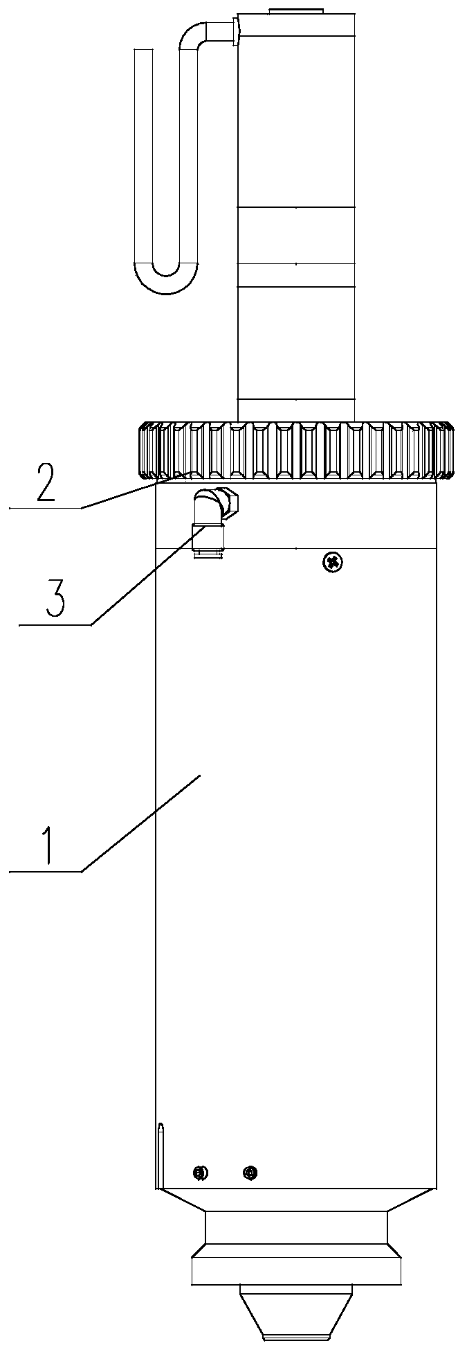
technical field [0001] The invention relates to the technical field of additive manufacturing, in particular to a transparent powder bucket device applied to additive manufacturing. Background technique [0002] Additive manufacturing technology refers to the "printing" of powder materials on the surface of objects to form the required surface layer or directly form the desired object, such as 3D printing, cladding equipment, etc. On the related equipment of additive manufacturing, it is necessary to use the powder bucket to load the printing powder required for printing to facilitate subsequent printing operations. [0003] The structure of the existing powder bucket device is as follows: figure 1 As shown, it includes the powder bucket body 1a, the lower powder seat fixed on the bottom of the powder bucket body 1a, the bucket cover 2a screwed on the top of the powder bucket body 1a, and the air supply inner set on the powder bucket body 1a Air circuit device 3a for cavit...

Claims


Application Information

Patent Timeline
Patent Type & Authority Applications(China)
IPC IPC(8): B29C64/153B29C64/255B29C64/386B33Y40/00B33Y50/00
CPCB29C64/153B29C64/255B29C64/386B33Y40/00B33Y50/00
Inventor 亢荣飞黎作瑜阳义
Owner 成都青石激光科技有限公司
Learn More