
Operation method of electrostatic field oil-water separation system

A technology of oil-water separation and operation method, which is applied in the direction of electric liquid separation, etc., which can solve the problems of increased operation and maintenance costs, increased floor space, and high environmental protection pressure, so as to reduce sewage treatment costs and environmental protection pressure, and reduce operating costs. Maintenance cost and the effect of reducing the height of the emulsified layer

Active Publication Date: 2013-12-18
LUOYANG RUIMING PETROCHEM TECH
View PDF7 Cites 11 Cited by
  • Summary
  • Abstract
  • Description
  • Claims
  • Application Information

AI Technical Summary

Problems solved by technology

[0003] At present, as most oilfields in China enter the late stage of production, on the one hand, the water content of the produced fluid increases. For example, the maximum water content of the produced fluid in Gudao Oilfield has reached 98%, and the water content of the produced fluid in some offshore oilfields can reach 99%. On the one hand, the trend of heavy and inferior crude oil in the late stage of exploitation is becoming more and more obvious. For example, the highest density of crude oil in Tahe Oilfield has exceeded 1g / cm3, and the density of Shengli ultra-heavy oil has also exceeded 1g / cm3: In addition, the oil recovery during deep mining The extensive use of additives has led to serious oil-water emulsification of the produced fluid in many oilfields, which has brought many problems to conventional oil-water separation: (1) The operation of electric dehydration equipment is unstable. Due to the high water content, poor properties and serious emulsification of the produced fluid, after After conventional oil-water separation, the water content may be high, and entering the electric dehydration equipment will cause the current to rise or even trip, which will affect the safe and stable operation of the electric dehydration equipment. At the same time, high current will increase the power consumption of the electric dehydration equipment; (2) The number of equipment stages Many, large area and high investment. Due to the low efficiency of conventional oil-water separation equipment, multi-stage separation is required to meet the water content requirements of crude oil, which will inevitably lead to a large number of equipment, increased floor space, and increased operation and maintenance costs; (3) The pressure on environmental protection is high. The poor quality of crude oil and the application of oil recovery additives lead to serious emulsification of crude oil production fluid. In addition, the conventional oil-water separation effect is poor, which will lead to excessive oil content in drainage, which will bring great pressure to sewage treatment and environmental protection.
[0005] The patent document with the application number 92208130.1 discloses a downhole oil-water separation and production device. The equipment consumes a lot of power during operation. After oil-water separation of high-water content well fluid, the water content is large and pollutes the environment.

Method used


Image

  • Operation method of electrostatic field oil-water separation system
  • Operation method of electrostatic field oil-water separation system
  • Operation method of electrostatic field oil-water separation system

Examples


Embodiment 1

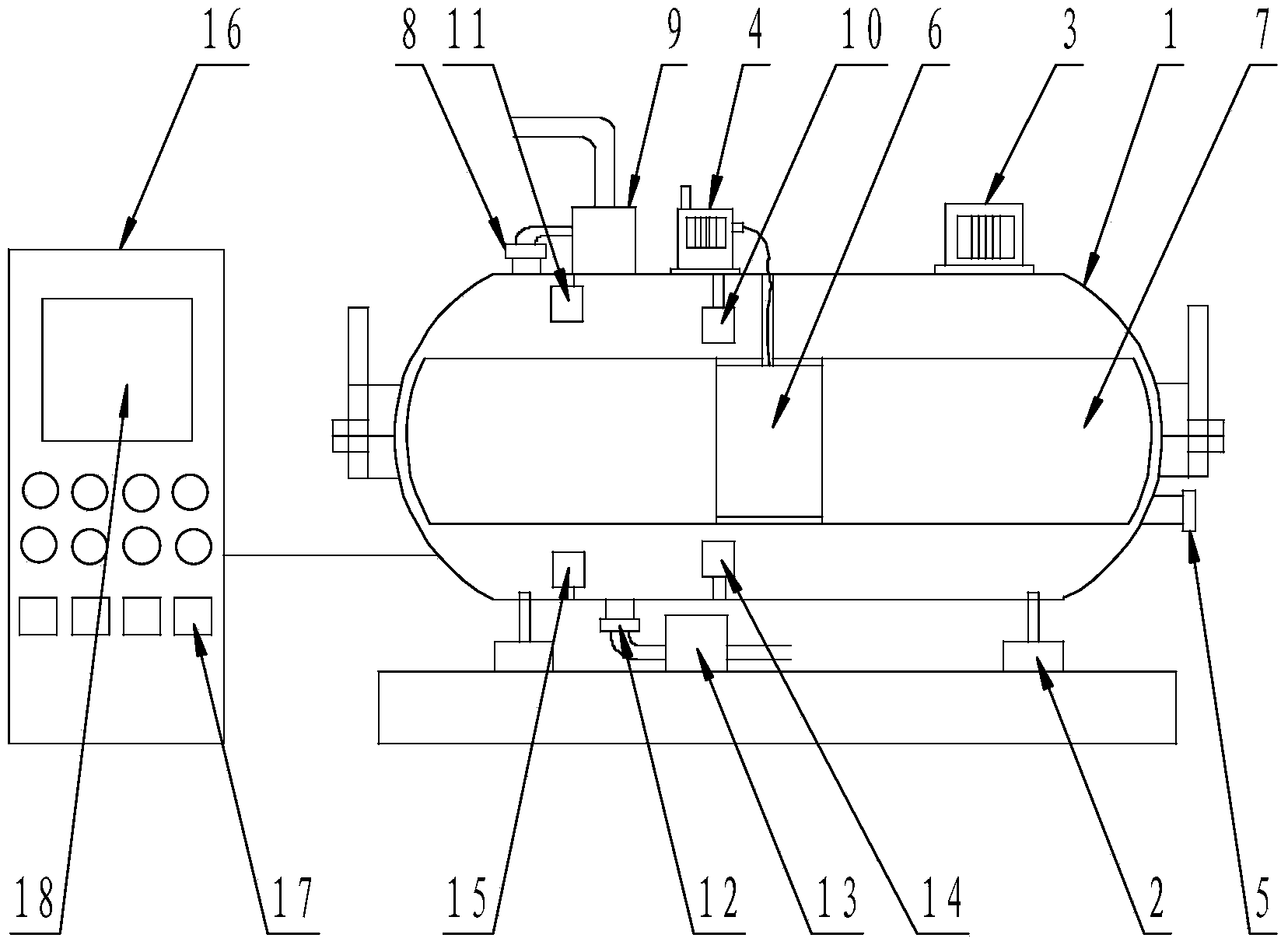
[0028] The degassed well fluid enters the oil-water separation tank 1 from the degassed oil liquid input port 5. When the degassed well fluid in the oil-water separation tank 1 reaches the set standard, the valve of the degassed oil liquid input port 5 is closed, and the oil, water, Oil sludge is preliminarily separated by sedimentation, and the pressure machine 3 is opened to increase the air pressure in the oil-water separation tank 1. Under the action of pressure, oil, water, and oil sludge are further separated.

Embodiment 2

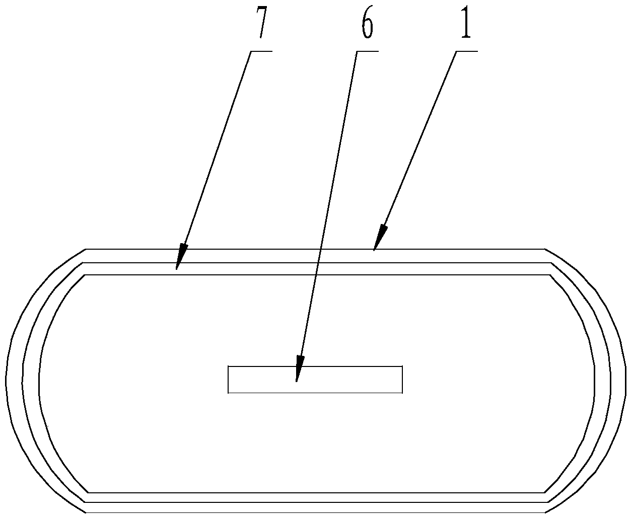
[0030] The control box 16 adjusts the voltage to the transformer 4, and outputs the voltage to the positive electrode plate 6 and the negative electrode ring electrode plate 7 through the wires, so that an electrostatic field space is formed between the positive electrode plate 6 and the negative electrode ring electrode plate 7, and the positive electrode plate Oil is separated from water within the electrostatic field of plate 6 and negative ring electrode plate 7 .

Embodiment 3

[0032] The upper pressure sensor 10 measures the upper pressure value in the oil-water separation tank 1, the lower pressure sensor 14 measures the lower pressure value in the oil-water separation tank 1, the upper pressure value and the lower pressure value are transmitted to the adapter module 17 through wires, and the adapter module 17 After the pressure value signal is converted, it is input to the central computer 18, and the central computer 18 calculates the pressure difference between the upper and lower sides of the oil-water separation tank 1, and obtains the position of the oil-water interface in the oil-water separation tank 1, and adjusts the pressure machine 3 so that the oil-water interface is located in the electrostatic field space of the middle.


PUM


Abstract

The invention relates to an operation method of an electrostatic field oil-water separation system. The electrostatic field oil-water separation system comprises an oil-water separation tank, a support, a press machine, a transformer, a degassed oil input port, an anode electrode plate, an annular cathode electrode plate, an oil outlet, an oil pumping pump, an upper pressure sensor, an upper dielectric constant sensor, an oil mud outlet, an oil mud pumping pump, a lower pressure sensor, a lower dielectric constant sensor, a control cabinet, an adapter module and a central computer. The operation method of the electrostatic field oil-water separation system has the advantages that the problems that crude oil dehydration rate is low, massive oil is contained in discharged water and energy consumption is high are solved, so that space of an electrostatic field is expanded, dehydration time of crude oil in the electrostatic field is shortened, dehydration efficiency is effectively improved, operation power consumption is reduced, production cost is reduced, energy conservation and environmental protection are achieved, height of an emulsion layer is effectively reduced, oil contained in the discharged water is reduced, sewage treatment cost and environmental protection pressure are reduced, structure is simple, operation is convenient, design thought is simple, an electrostatic field separation effect is good, and the operation method of the electrostatic field oil-water separation system is applicable to popularization and application.

Description

technical field [0001] The invention relates to the technical field of crude oil-water separation, in particular to an operating method of an electrostatic field oil-water separation system. [0002] Background technique [0003] At present, as most oilfields in China enter the late stage of production, on the one hand, the water content of the produced fluid increases. For example, the maximum water content of the produced fluid in Gudao Oilfield has reached 98%, and the water content of the produced fluid in some offshore oilfields can reach 99%. On the one hand, the trend of heavy and inferior crude oil in the late stage of exploitation is becoming more and more obvious. For example, the highest density of crude oil in Tahe Oilfield has exceeded 1g / cm3, and the density of Shengli ultra-heavy oil has also exceeded 1g / cm3: In addition, the oil recovery during deep mining The extensive use of additives has led to serious oil-water emulsification of the produced fluid in man...

Claims


Application Information

Patent Timeline
Patent Type & Authority Applications(China)
IPC IPC(8): B01D17/06
Inventor 李瑞强吴洲
Owner LUOYANG RUIMING PETROCHEM TECH
Learn More