
Drilling positioning mechanism and drilling machine with mechanism

The technology of a positioning mechanism and a drilling machine is applied to the drilling machine. , In the field of drilling positioning mechanism, it can solve problems such as errors and inability to effectively guarantee drilling accuracy, and achieve the effects of stable and reliable movement, improved drilling accuracy, and improved flexibility

Active Publication Date: 2020-04-10
SHANDONG FUYUAN TRACK MACHINERY CO LTD
View PDF7 Cites 3 Cited by
  • Summary
  • Abstract
  • Description
  • Claims
  • Application Information

AI Technical Summary

Problems solved by technology

[0003] In order to avoid deflection, the position of the hole needs to be positioned when drilling with a drilling machine. In the prior art, the above-mentioned work is done manually, so there is a certain error, and the drilling accuracy cannot be effectively guaranteed.

Method used


Image

  • Drilling positioning mechanism and drilling machine with mechanism
  • Drilling positioning mechanism and drilling machine with mechanism
  • Drilling positioning mechanism and drilling machine with mechanism

Examples


Embodiment 1

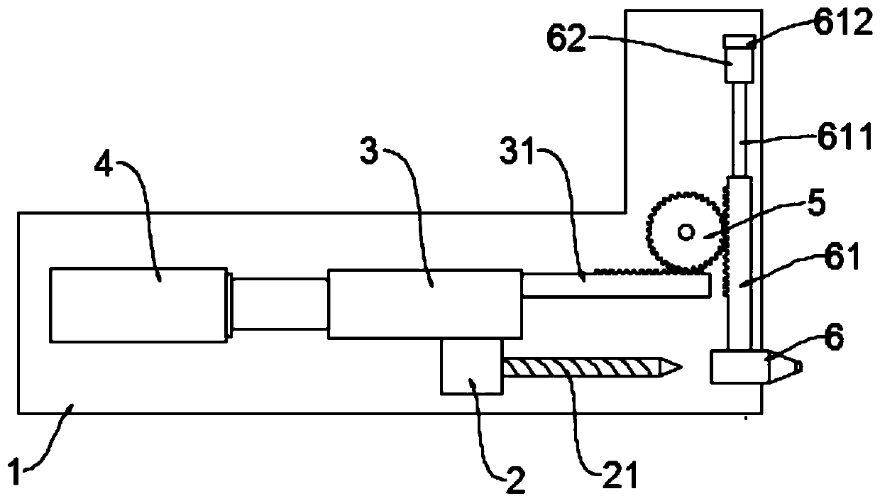
[0023] see Figure 1-2 , in an embodiment of the present invention, a drilling positioning mechanism includes a base 1 and a drilling motor 2; The mounting base 3 is slidably connected to the base 1 and can move along the length direction of the drill rod 21. The base 1 is equipped with a feeder 4 that drives the mounting base 3. When in use, the drilling motor 2 drives the drill rod 21 rotates, and then the feed device 4 drives the mounting seat 3 to move, thereby completing the feeding work to realize feeding.

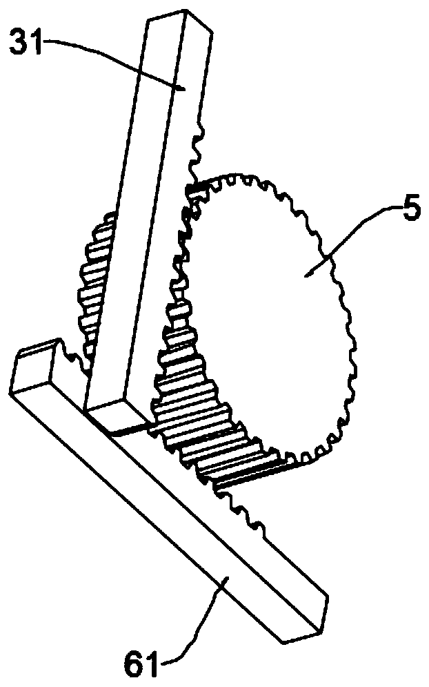
[0024] One end of the same side of the mounting seat 3 and the drill rod 21 is fixed with a first rack 31, and the base 1 is rotatably connected with a gear 5 meshing with the first rack 31; The side is provided with a second rack 61 meshing with it, the first rack 31 and the second rack 61 are out of position and vertical, the bottom of the second rack 61 is fixed with a laser emitter 6, and the laser generator 6 is slidably connected to the base 1 and can move al...

Embodiment 2

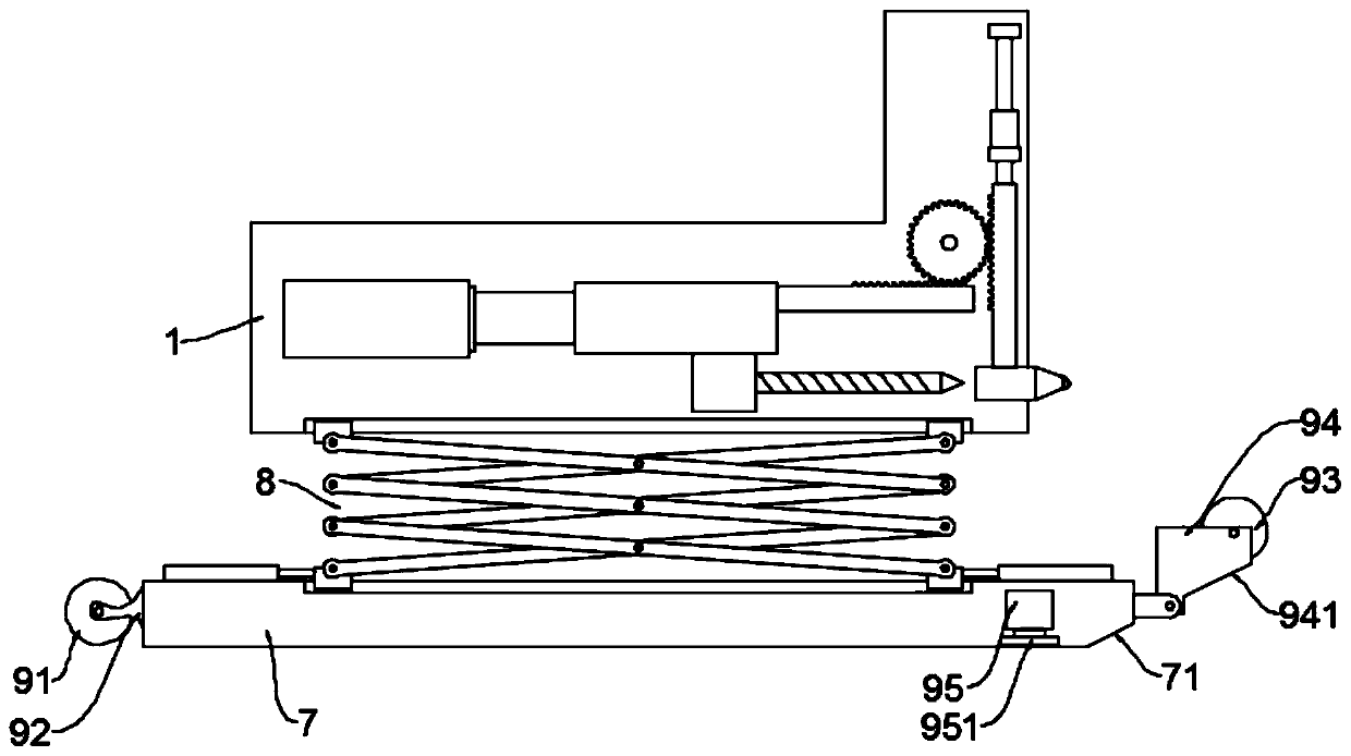
[0029] see Figure 3-4 , in an embodiment of the present invention, a drilling device includes the drilling positioning mechanism as described in Embodiment 1, and also includes a base 7; the base 7 is connected to the base 1 through a lifting mechanism 8, and can The height of the base can be adjusted to meet different construction needs. The base 7 is also equipped with a moving mechanism to facilitate the movement of the whole device and improve the flexibility of use.

[0030] The specific mechanism of the lifting mechanism 8 is not limited. Preferably, in this embodiment, the lifting mechanism 8 is a scissor lift.

[0031] Specifically, in this embodiment, the moving mechanism includes a rear support wheel 91 and a front support wheel 93, wherein the rear support wheel 91 is installed on the rear support frame 92 fixed on the base 7, and the front support wheel 93 is installed on the front support wheel 93. On the frame 94, the front support frame 94 is rotationally conn...


PUM


Abstract

The invention discloses a drilling positioning mechanism and a drilling machine with the mechanism. The drilling positioning mechanism comprises a base and a drilling motor. The side, located on the same side with a drilling rod, of a mounting base is fixedly provided with a first rack, the base is rotatably connected with a gear engaged with the first rack, the side, away from the drill rod, of the gear is provided with a second rack, the first rack and the second rack are in heterotopia perpendicular, the bottom of the second rack is fixedly provided with a laser emitter, the laser emitter is limited by a limiting assembly, when the laser emitter is located on the maximum downward moving stroke, the drilling rod and the laser emitter are coaxial, through the laser emitter, positioning ofdrilling can be assisted, drilling precision can be improved, through cooperative use of the first rack, the second rack and the gear, the laser emitter can be coaxial with the drilling rod during positioning, and positioning effect can be improved. Meanwhile, in the feeding process of the drilling rod, the laser emitter can be staggered from the drilling rod, and normal feeding of the drilling rod can be ensured.

Description

technical field [0001] The invention relates to the field of building decoration equipment, in particular to a drilling positioning mechanism and a drilling machine with the mechanism. Background technique [0002] In the process of building decoration construction, it is often necessary to use a drilling machine to drill holes on the wall to install the decorative parts. [0003] In order to avoid deflection, the position of the hole needs to be positioned when drilling with a drilling machine. In the prior art, the above-mentioned work is all done manually, so there is a certain error, and the drilling accuracy cannot be effectively guaranteed. Contents of the invention [0004] The object of the present invention is to provide a drilling positioning mechanism and a drilling machine with the mechanism, so as to solve the above problems. [0005] To achieve the above object, the present invention provides the following technical solutions: [0006] A drilling positionin...

Claims


Application Information

Patent Timeline
Patent Type & Authority Applications(China)
IPC IPC(8): B28D1/14B28D7/00
CPCB28D1/14B28D1/146B28D7/00
Inventor 张小友
Owner SHANDONG FUYUAN TRACK MACHINERY CO LTD
Learn More