
Manipulator structure and robot capable of achieving switching between adsorption and clamping modes

A manipulator, dual-mode technology, applied in the field of stacking robots, can solve problems such as the inability to achieve multiple modes of work and switching, and a single working mode.

Inactive Publication Date: 2020-04-10
苏州海翌智能科技有限公司
View PDF7 Cites 5 Cited by
  • Summary
  • Abstract
  • Description
  • Claims
  • Application Information

AI Technical Summary

Problems solved by technology

[0009] However, most of the currently used manipulators only have a single working mode, and cannot realize multi-mode work and switching. It is necessary to design a manipulator structure and robot that can realize dual-mode switching of adsorption and gripping.

Method used


Image

  • Manipulator structure and robot capable of achieving switching between adsorption and clamping modes
  • Manipulator structure and robot capable of achieving switching between adsorption and clamping modes
  • Manipulator structure and robot capable of achieving switching between adsorption and clamping modes

Examples


Embodiment 1

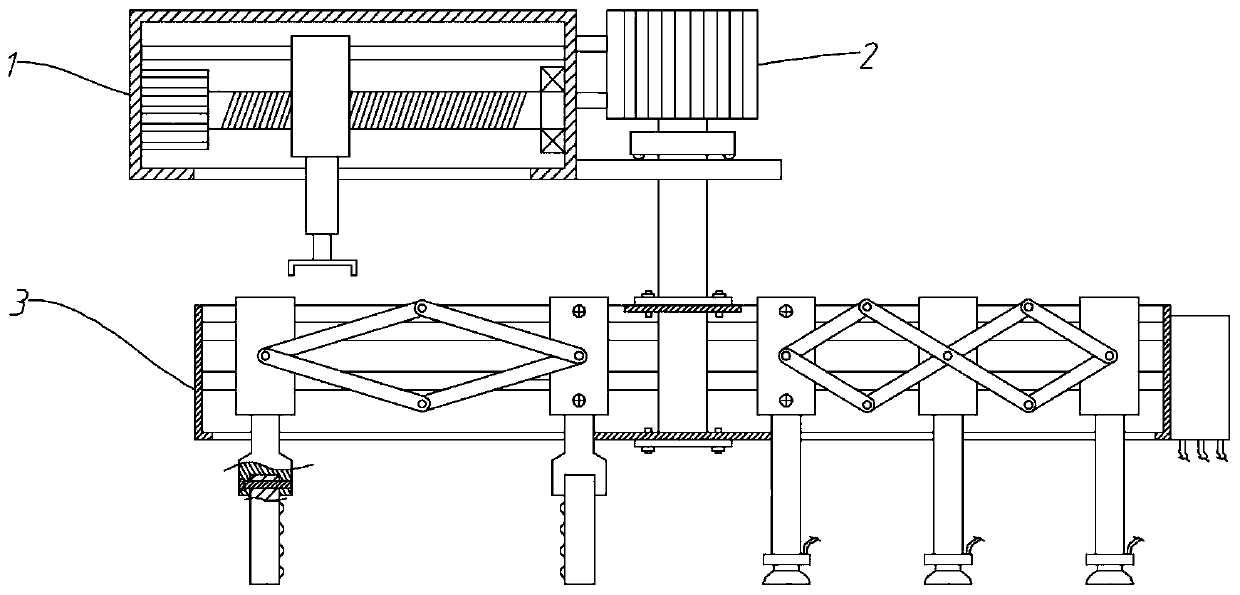
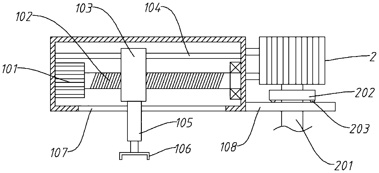
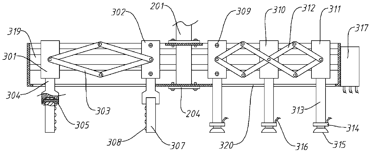
[0049] A manipulator structure capable of switching between two modes of adsorption and gripping, including a screw box 1 and an execution unit;

[0050] The screw box 1 includes a box body, No. 1 servo motor 101, screw mandrel 102, moving nut 103, No. 1 hydraulic cylinder 105 and chuck 106; No. 1 servo motor 101 is installed on the left side wall inside the box body, and No. 1 servo motor The output end of 101 protrudes horizontally to the right and is connected with a screw rod 102, the right end of the screw rod 102 is rotationally connected with the right side wall of the box; the moving nut 103 is screwed on the screw rod 102, and a No. 1 hydraulic cylinder 105 is installed at the bottom of the moving nut 103 , the telescopic end of the No. 1 hydraulic cylinder 105 protrudes downwards from the box and is connected with a chuck 106; the bottom of the box corresponds to the moving path of the moving nut 103 and has a corresponding type of slideway 101;

[0051] The executio...

Embodiment 2

[0054] A manipulator structure capable of switching between two modes of adsorption and gripping, including a screw box 1 and an execution unit;

[0055] The screw box 1 includes a box body, No. 1 servo motor 101, screw mandrel 102, moving nut 103, No. 1 hydraulic cylinder 105 and chuck 106; No. 1 servo motor 101 is installed on the left side wall inside the box body, and No. 1 servo motor The output end of 101 protrudes horizontally to the right and is connected with a screw rod 102, the right end of the screw rod 102 is rotationally connected with the right side wall of the box; the moving nut 103 is screwed on the screw rod 102, and a No. 1 hydraulic cylinder 105 is installed at the bottom of the moving nut 103 , the telescopic end of the No. 1 hydraulic cylinder 105 protrudes downwards from the box and is connected with a chuck 106; the bottom of the box corresponds to the moving path of the moving nut 103 and has a corresponding type of slideway 101;

[0056] The executio...

Embodiment 3

[0060] A manipulator structure capable of switching between two modes of adsorption and gripping, including a screw box 1 and an execution unit;

[0061] The screw box 1 includes a box body, No. 1 servo motor 101, screw mandrel 102, moving nut 103, No. 1 hydraulic cylinder 105 and chuck 106; No. 1 servo motor 101 is installed on the left side wall inside the box body, and No. 1 servo motor The output end of 101 protrudes horizontally to the right and is connected with a screw rod 102, the right end of the screw rod 102 is rotationally connected with the right side wall of the box; the moving nut 103 is screwed on the screw rod 102, and a No. 1 hydraulic cylinder 105 is installed at the bottom of the moving nut 103 , the telescopic end of the No. 1 hydraulic cylinder 105 protrudes downwards from the box and is connected with a chuck 106; the bottom of the box corresponds to the moving path of the moving nut 103 and has a corresponding type of slideway 101;

[0062] The executio...


PUM


Abstract

The invention relates to the technical field of stacking robots, in particular to a manipulator structure and robot capable of achieving switching between adsorption and clamping modes; according to the manipulator structure, a wok box is rotated though a No. 2 servo motor, and the right part of the work box is provided with an adsorption assembly; the left part of the work box is provided with aclamping assembly, right and left switching is performed though rotation of the work box, so that the clamping assembly or the adsorption assembly corresponds to a screw box; the screw box is arranged, and a screw is driven by a No. 1 servo motor to rotate; a movable nut is moved along the axial direction of the screw, so that a clip is driven to move; the up-down position of the clip is regulatedthrough a No. 1 hydraulic cylinder to cooperate with the clamping assembly or the adsorption assembly; when the clamping assembly is rotated to the position below the screw box, the clip is regulatedfor clamping a type I sliding seat II; then, the position of the movable nut is regulated, and the type I sliding seat is changed with the movable nut, so that the spacing between clamping plates ischanged; the clamping of articles is achieved; and the adsorption assembly is kept away based on negative pressure, and used for adsorbing the articles through suction force generated by a negative sucker through a negative pressure pump.

Description

technical field [0001] The invention relates to the technical field of stacking robots, in particular to a manipulator structure and a robot capable of switching between two modes of adsorption and gripping. Background technique [0002] A robot is a machine device that performs work automatically. It can accept human command, run pre-programmed programs, and act according to principles formulated with artificial intelligence technology. Its mission is to assist or replace human work in jobs such as manufacturing, construction, or hazardous jobs. [0003] It is said that robots mostly refer to a set of devices composed of actuators, driving devices, detection devices, control systems and complex machinery. [0004] Among them, the executive mechanism mostly adopts a manipulator, which is an automatic operation device that can imitate certain action functions of the human hand and arm to grab, carry objects or operate tools according to a fixed program. The feature is that...

Claims


Application Information

Patent Timeline
Patent Type & Authority Applications(China)
IPC IPC(8): B25J15/00
CPCB25J15/0057
Inventor 张扬
Owner 苏州海翌智能科技有限公司
Learn More