
Anti-loosening method and device for pile hammer head

A technology for preventing loosening and piling hammer, which is applied in the direction of threaded fasteners, connecting components, screws, etc., which can solve the problems of low connection strength, easy loosening, and loose inner nut and connecting body.

Pending Publication Date: 2020-04-07
GUANGDONG LIYUAN HYDRAULIC MACHINERY
View PDF1 Cites 0 Cited by
  • Summary
  • Abstract
  • Description
  • Claims
  • Application Information

AI Technical Summary

Problems solved by technology

[0005] The above-mentioned scheme has improved the problem that the existing bolts and nuts are easily loosened to a certain extent. Although the above-mentioned scheme is provided with several anti-skid grooves on the opposite top surfaces of the inner nut and the outer nut, the inner nut, the outer nut, and the bolts are not fixed. The starting point of the thread is uncertain, and the anti-skid groove is difficult to achieve the purpose of being locked together
Even if it can be accidentally stuck together, but when applied to a piling hammer head with a high-load dynamic vibration structure, this solution still has low connection strength. When the vibration is large, there is a gap between the inner nut and the outer nut or the inner nut is easy to push the outer nut. Backoff causes looseness between the inner nut and the connecting body, and eventually causes the outer nut and inner nut to come off the bolt
In particular, the structural design, which bears limited alternating loads, is not suitable for anti-loosening of heavy-duty pile driver hammer heads

Method used


Image

  • Anti-loosening method and device for pile hammer head
  • Anti-loosening method and device for pile hammer head
  • Anti-loosening method and device for pile hammer head

Examples


Embodiment Construction

[0049] Embodiments of the present invention will be described in detail below.

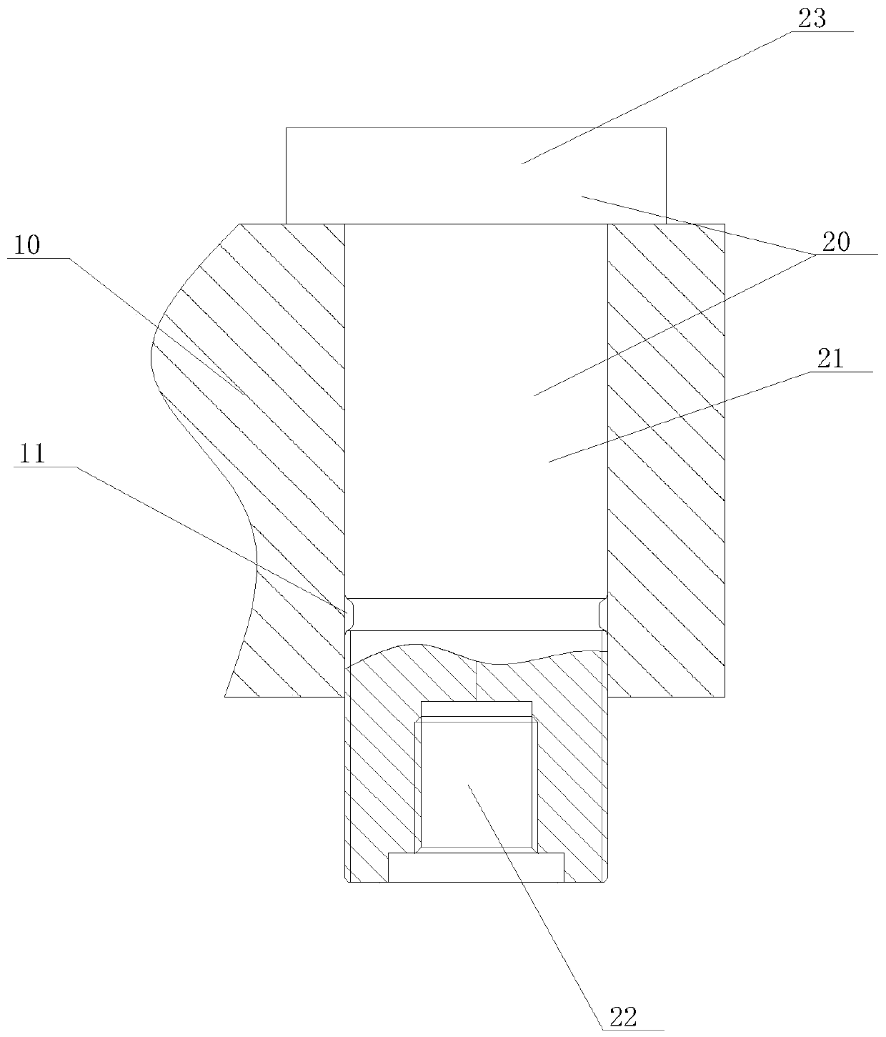
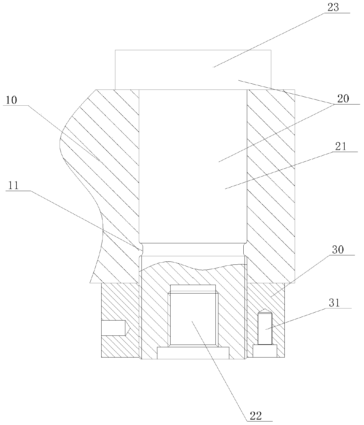
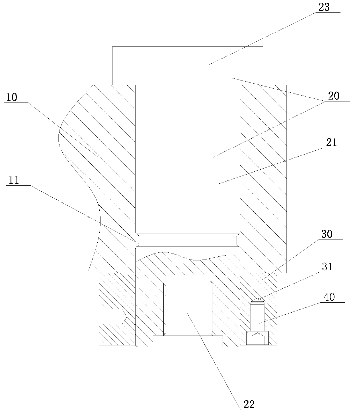
[0050] Such as Figure 1 to Figure 5 As shown, a kind of piling hammerhead anti-loosening method provided by the present invention comprises the following steps:

[0051] (1), such as figure 1 As shown, the pin shaft 20 of the anti-loosening device for the piling hammer is threaded through the shaft hole 11 of the assembly 10 and the nut 30 through the pin bolt 21; wherein, the anti-loosening device for the piling hammer includes the assembly 10, the pin 20. Nut 30, hexagon socket head cap screw 40, end flange 50, pin shaft 20 includes pin bolt 21, pin cover 23, the outer surface of pin bolt 21 has the first external thread, and the lower end surface of pin bolt 21 is provided with The first screw hole 22, the first screw hole 22 has a first internal thread, the thread direction of the first internal thread is opposite to that of the first external thread; the lower end surface of the nut 30 is ...


PUM


Abstract

The invention relates to the manufacturing technology of heavy pile foundation engineering equipment, and discloses an anti-loosening method of a pile hammer head. The method comprises the following steps of: firstly, enabling a pin bolt of a pin shaft to penetrate through a shaft hole of an assembly body to be in threaded connection with a nut; screwing the nut again, and then screwing a hexagonsocket head cap screw into a second screw hole in the lower end face of the nut, screwing and installing the end flange in a first screw hole, aligning the hexagon socket head cap screw with a counterbore in the end cover, then reversely or forwards rotating the hexagon socket head cap screw to allow the hexagon socket head cap screw to extend into a counter bore, and limiting and clamping the lower end of the hexagon socket head cap screw and the counter bore. The invention further discloses a device for implementing the method. By means of the unique structure and process design, the nut can be effectively prevented from loosening from the pin shaft, the method and the device can be widely applied to manufacturing of heavy pile drivers, indexes such as stability and safety of heavy pilefoundation equipment can be remarkably improved, and the heavy pile foundation equipment can reach the international advanced technical level.

Description

technical field [0001] The invention relates to the technical field of manufacturing heavy-duty pile foundation engineering equipment, in particular to a method and device for preventing loosening of a piling hammer head. Background technique [0002] At present, in the process of building pile foundation construction, it is often necessary to use piling hammers for pile foundation pile construction. Commonly used piling hammers include hydraulic hammers, hydraulic vibration hammers, diesel hammers, etc., because the piling hammer head is a high-load dynamic vibration structure, so The fastening of its assembly structure is especially important. Once the fasteners of the assembly structure loosen, it will cause major safety accidents and major economic losses. Especially for heavy engineering equipment and large ocean engineering equipment, due to the harsh construction environment and long continuous operation time, higher requirements are put forward for the stability and ...

Claims


Application Information

Patent Timeline
IPC IPC(8): F16B39/04F16B21/04
CPCF16B39/04F16B21/04Y02E30/30
Inventor 魏智健张兰
Owner GUANGDONG LIYUAN HYDRAULIC MACHINERY
Learn More