
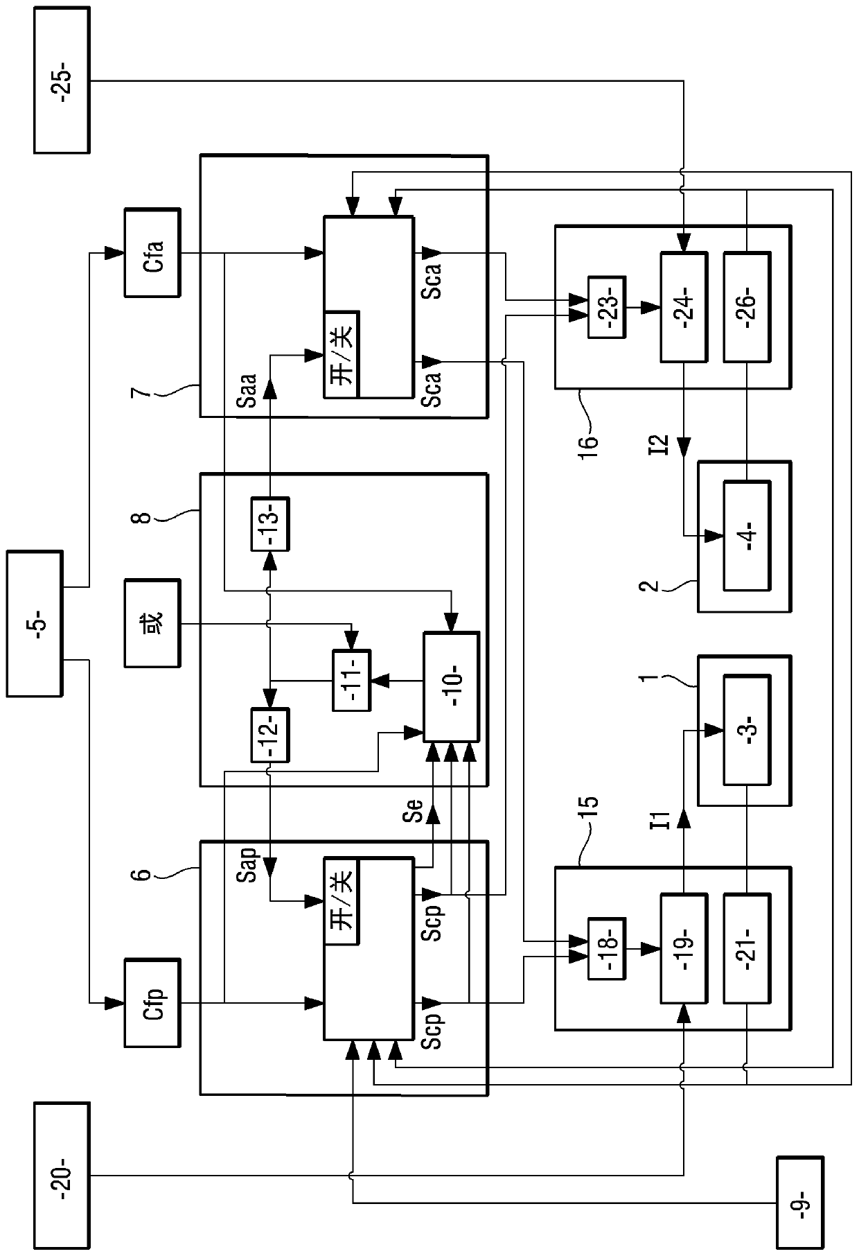
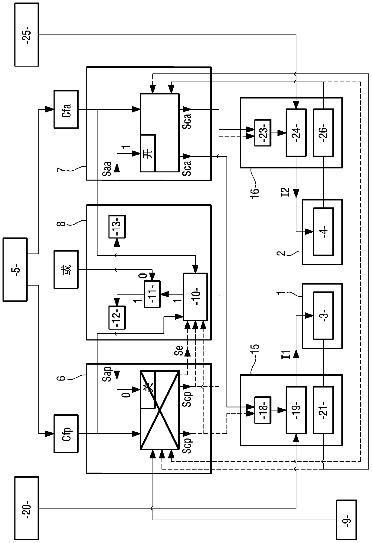
Architecture of an aircraft braking system

A braking system, aircraft technology, applied in the direction of braking control system, aircraft braking arrangement, ABS control system, etc., can solve the problem of not providing potential error protection and so on

Active Publication Date: 2020-04-07
SAFRAN LANDING SYSTEMS
View PDF8 Cites 2 Cited by
  • Summary
  • Abstract
  • Description
  • Claims
  • Application Information

AI Technical Summary

Problems solved by technology

However, it does not provide protection against potential errors leading to failures that may arise from specific operating conditions that were not anticipated at the development stage and that affect, for example, the control logic

Method used


Image

  • Architecture of an aircraft braking system
  • Architecture of an aircraft braking system
  • Architecture of an aircraft braking system

Examples


Embodiment Construction

[0035] refer to figure 1 , the braking system architecture according to a first embodiment of the invention comprises brakes intended to brake the so-called "braking" wheels of the landing gear of the aircraft. The brake comprises a friction member (e.g. a stack of carbon discs), and a first electromechanical actuator 1 and a second electromechanical actuator 2 adapted to apply A braking force is applied to the friction member. The first electromechanical actuator 1 comprises a first electric motor 3 and the second electromechanical actuator 2 comprises a second electric motor 4 .

[0036] The first electric motor 3 and the second electric motor 4 are controlled by braking commands generated eg by the pilot of the aircraft 5 or by an automatic braking system. The braking command is transformed into a main braking command Cfp and an alternative braking command Cfa representing the braking command and generated via different mechanisms to prevent common mode failures between t...


PUM


Abstract

Disclosed is an architecture of an aircraft braking system, including: brakes including electromechanical actuators (1,2); a main control channel (6) and an alternative control channel (7), wherein the main control channel (6) and the alternative control channel (7) comprise electrical components at least partly different and adapted to provide at least partly different main brake control functions and alternative brake control functions, power modules (15, 16), wherein the power modules (15, 16) comprise electrical components at least partly different and adapted to generate supply current (I1, I2) based on the main control signal or an alternative control signal, a supervision unit (8). The supervision unit (8) is adapted to ensure that the main control signal is used in normal operationand that the replacement control signal is used to generate the supply current in the event of a fault.

Description

technical field [0001] The invention relates to the field of aircraft braking system architecture. Background technique [0002] Aircraft electrical braking system architectures typically include a plurality of brakes, each intended to brake a wheel of the aircraft's landing gear. [0003] Each brake comprises a friction member and independent electromechanical actuators (typically four actuators) intended to apply a braking force to the friction member and thus a braking torque on the wheel. [0004] The architecture also includes a control channel that receives braking commands from the pilot and converts them into control signals, and a power module that generates supply current for powering the electric motors of the electromechanical actuators from the control signals. [0005] Given the number of independent electromechanical actuators used for braking, this architecture naturally and inherently has a high level of redundancy. [0006] This high level of redundancy i...

Claims


Application Information

Patent Timeline
Patent Type & Authority Applications(China)
IPC IPC(8): B64C25/44B60T13/74
CPCB64C25/44B60T13/741B60T8/1703B60T8/885B64C25/42B64C25/46B60T2270/406B60T8/175B60T8/176B60T2270/10B60T2270/20B60T2270/402B60T2270/403
Inventor D·恩夫罗伊O·弗雷B·戈耶兹
Owner SAFRAN LANDING SYSTEMS
Learn More