
Cleaning device for underwater instrument

A technology for cleaning devices and instruments, which is applied in the field of cleaning/wiping devices, and can solve the problems that cameras cannot provide stable/steady direction shooting, blurring, and practicality discounts, etc.

Inactive Publication Date: 2020-04-07
何恒春
View PDF10 Cites 1 Cited by
  • Summary
  • Abstract
  • Description
  • Claims
  • Application Information

AI Technical Summary

Problems solved by technology

[0002] According to common practice, as a photographic device for underwater surveillance, since there is no cleaning and wiping device that can be activated at a fixed time or manually, the lens will be polluted or covered by debris after a period of use and blurred, causing the photographic line of sight to be affected. Serious impact; moreover, some photographic equipment does not have lighting devices, resulting in insufficient clarity of the captured pictures; this kind of photographic equipment can only be effectively monitored in broad daylight with light; at night or when there is no sun, the picture is not clear Or it is dark, and it cannot provide clear monitoring images or correct information; in addition, the camera cannot provide stable position / direction to shoot objects in the water, which greatly reduces its practicality. This is what the industry and consumers desperately want to break through. place

Method used


Image

  • Cleaning device for underwater instrument
  • Cleaning device for underwater instrument
  • Cleaning device for underwater instrument

Examples


Embodiment Construction

[0035] The present invention is hereby combined with the accompanying drawings and described in detail as follows in the form of embodiments. The purpose of the drawings used in the text is only for illustration and auxiliary description, and may not be the true proportion and accuracy of the present invention after implementation. configuration, so the ratio and configuration relationship of the attached drawings should not limit the patent scope of the present invention in actual implementation, please explain first.

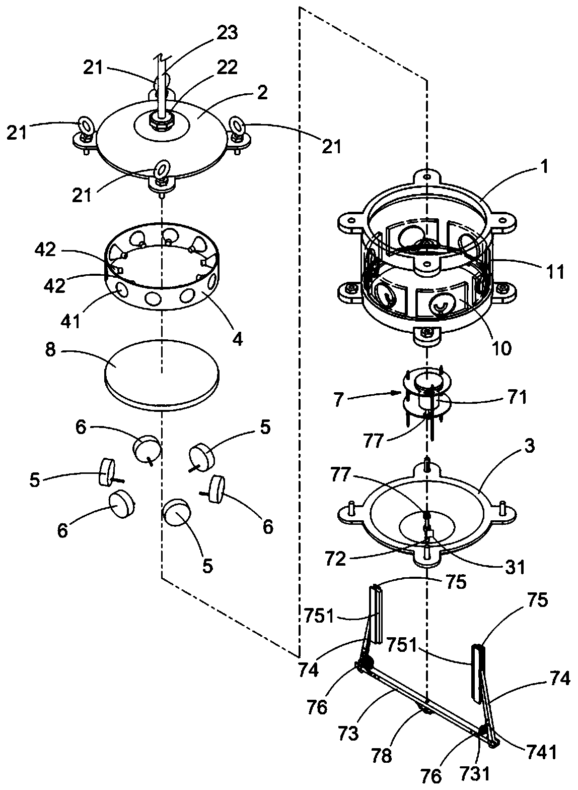
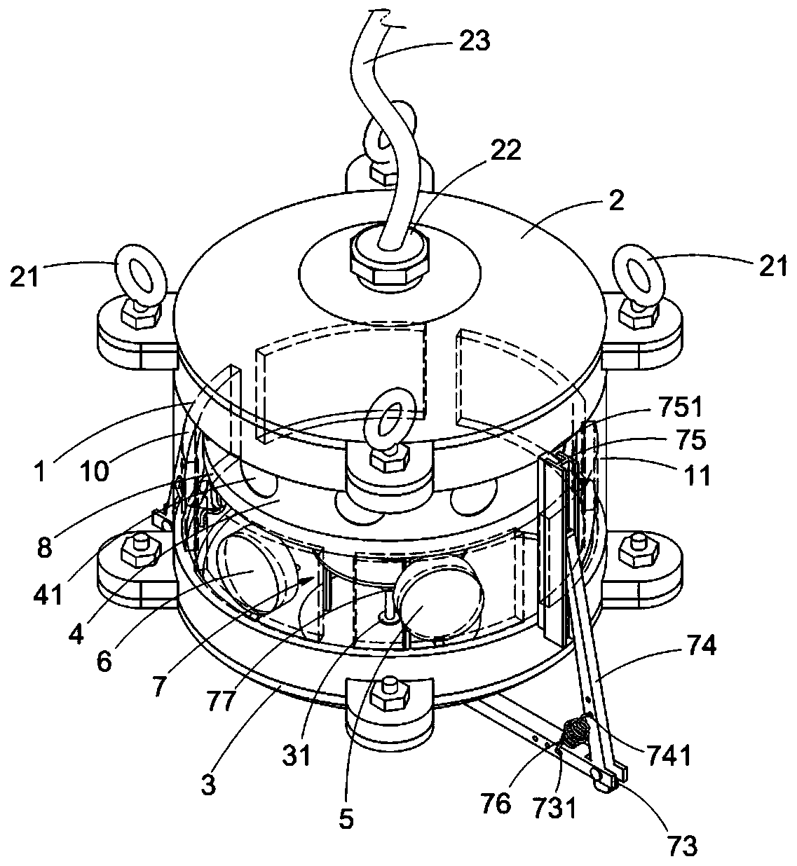
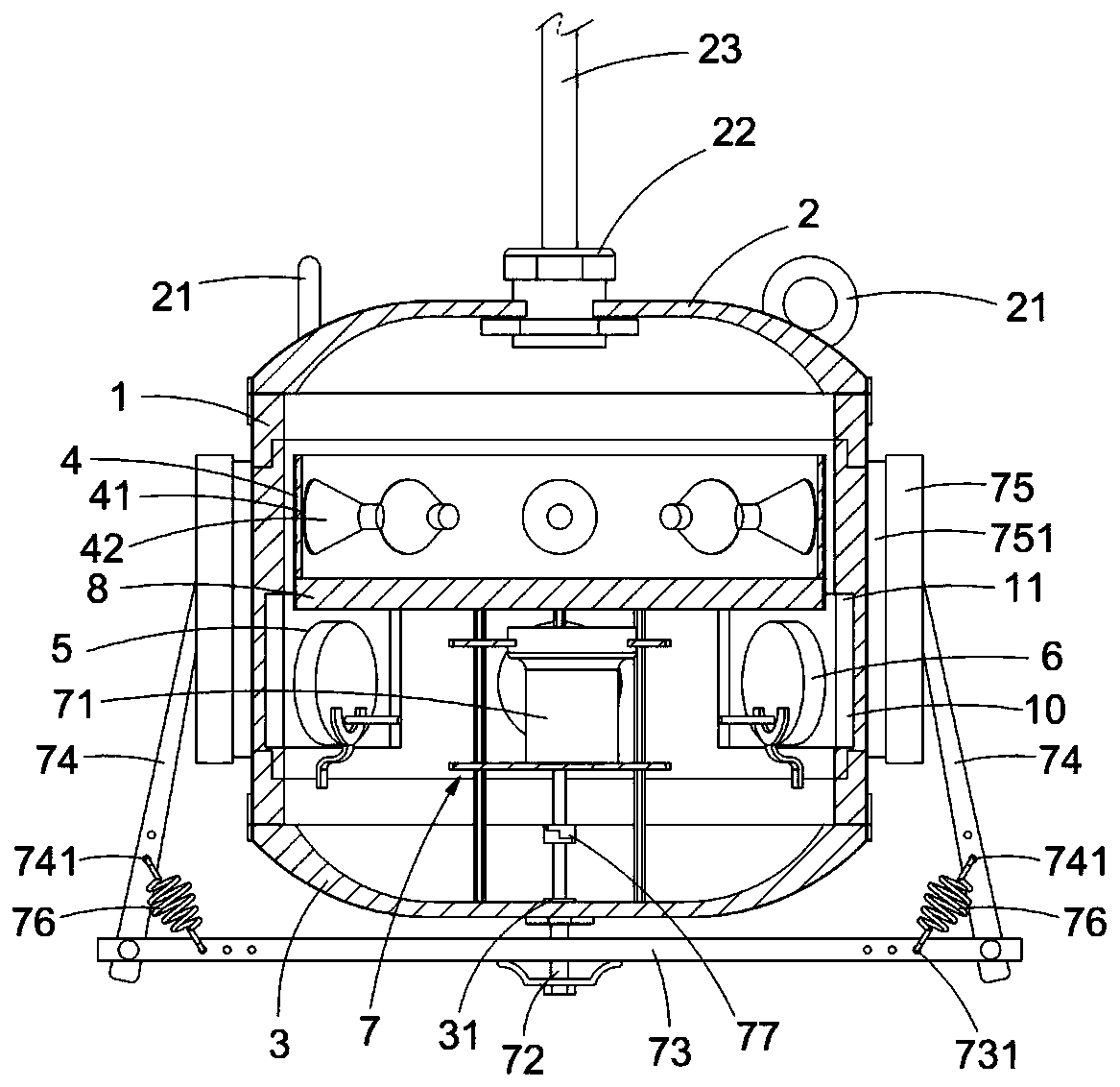
[0036] see Figure 1 to Figure 7 As shown, the cleaning / wiping device of the present invention for underwater monitoring / observation / scanning / photographing / sensing / detecting various signal collection instruments in a preferred embodiment includes a cabin body 1, A top cover 2 , a bottom cover 3 , a lamp set mount 4 , at least one first instrument set 5 , at least one second instrument set 6 , a motor support base 7 , and at least one wiper main frame 73 .

[00...


PUM


Abstract

The he invention discloses a cleaning device for an underwater instrument. An illuminating lamp set seat frame, an interval with at least one illuminating lamp set, at least one first instrument set and at least one second instrument set are arranged in a cabin body, wherein the first instrument set and the second instrument set are used for monitoring / observing / scanning / photographing / sensing / detecting various signal collection for detection and watching; the first instrument set and the second instrument set are arranged in detection and observation windows; a scraping and brushing mandrel with a closed shaft seal, a scraping and brushing main frame, a scraping and brushing support, a scraping and brushing base, a scraping and brushing piece and an elastic body are driven by a motor, andcleaning and wiping at any angle or at any set angle or at regular time or in real time or in a rotating or reciprocating mode are executed on the outer side (the water area side) of a detection observation window of a cabin body touched by the scraping and brushing piece. The cabin body is provided with a heat insulation device between an interval where the illuminating lamp set seat frame of theilluminating lamp set is located and another interval where the first instrument set and the second instrument set are located, so that the first instrument set and the second instrument set do not affect information collection and can work normally.

Description

technical field [0001] The invention relates to a cleaning / wiping device, which refers to a motor controlled by an electric control mechanism to drive a scraping mandrel with a sealed shaft seal, a scraping main frame, a scraping bracket, a scraping seat, a scraping brush, etc. sheet, elastic body, and can always maintain watertight and watertight in the cabin, wipe the sheet Any angle or setting angle or timing or real-time or rotating or reciprocating on the outside of the detection observation window (water side) for cleaning / wiping debris for underwater monitoring / observation / scanning / photography / sensing / detection in wired and wireless ways Cleaning / wiping device for various signal collecting instruments. Background technique [0002] According to common practice, as a photographic device for underwater surveillance, since there is no cleaning and wiping device that can be activated at a fixed time or manually, the lens will be polluted or covered by debris after a per...

Claims


Application Information

Patent Timeline
Patent Type & Authority Applications(China)
IPC IPC(8): B08B1/00B08B1/04B08B13/00F21V33/00
CPCB08B13/00F21V33/00B08B1/165B08B1/143B08B1/30B08B1/12B08B1/32
Inventor 何恒春
Owner 何恒春
Learn More