Extrusion device for sealing optical cable joint box and optical cable joint box

A technology of optical cable joint box and extrusion device, which is applied in the direction of light guide, optics, optical components, etc., can solve the problems of large lateral drop, inability to enter cables, and long routing channels, etc., to shorten the transition distance, reduce the lateral drop, and improve The effect of cable density

Active Publication Date: 2020-12-29
FENGHUO COMM SCI & TECH CO LTD
View PDF1 Cites 0 Cited by
  • Summary
  • Abstract
  • Description
  • Claims
  • Application Information

AI Technical Summary

Problems solved by technology

[0004] The first type is a cylindrical structure. Since the through grooves on the sealing section used for the passage of optical cables are distributed circularly, the transition from the optical fiber sealing section to the fiber disc is circular to square. This transition method has a large lateral drop , requires a long wiring channel, and the structure is not compact enough
[0005] The second type is a square cylindrical structure. Since the through grooves on the sealing section for the optical cable to pass through are distributed into two parallel straight lines, the transition from the optical fiber sealing section to the fiber disc is linear to square. Although this transition method solves the problem of The problem of the transverse drop from the sealing section of the optical fiber to the fiber reel is solved, but the space on both sides of the sealing section needs to be used to fix the lower box of the outer cylinder, so that no through groove can be opened, so the cable cannot be fed in. The disadvantage is that the cable feeding density is not as good as cylindrical structure
[0007] Patent application CN104641524A discloses a cable sealing unit with multiple sealing modules. When the sealing unit is sealed, it needs to use the handle to rotate to achieve extrusion sealing. Since the optical cable is arranged from bottom to top, the handle is in the During operation, it is bound to interfere with the optical cable, affecting the convenience of operation

Method used


Image

  • Extrusion device for sealing optical cable joint box and optical cable joint box
  • Extrusion device for sealing optical cable joint box and optical cable joint box
  • Extrusion device for sealing optical cable joint box and optical cable joint box

Examples


Embodiment Construction

[0052] The present invention will be described in further detail below in conjunction with the accompanying drawings and embodiments.

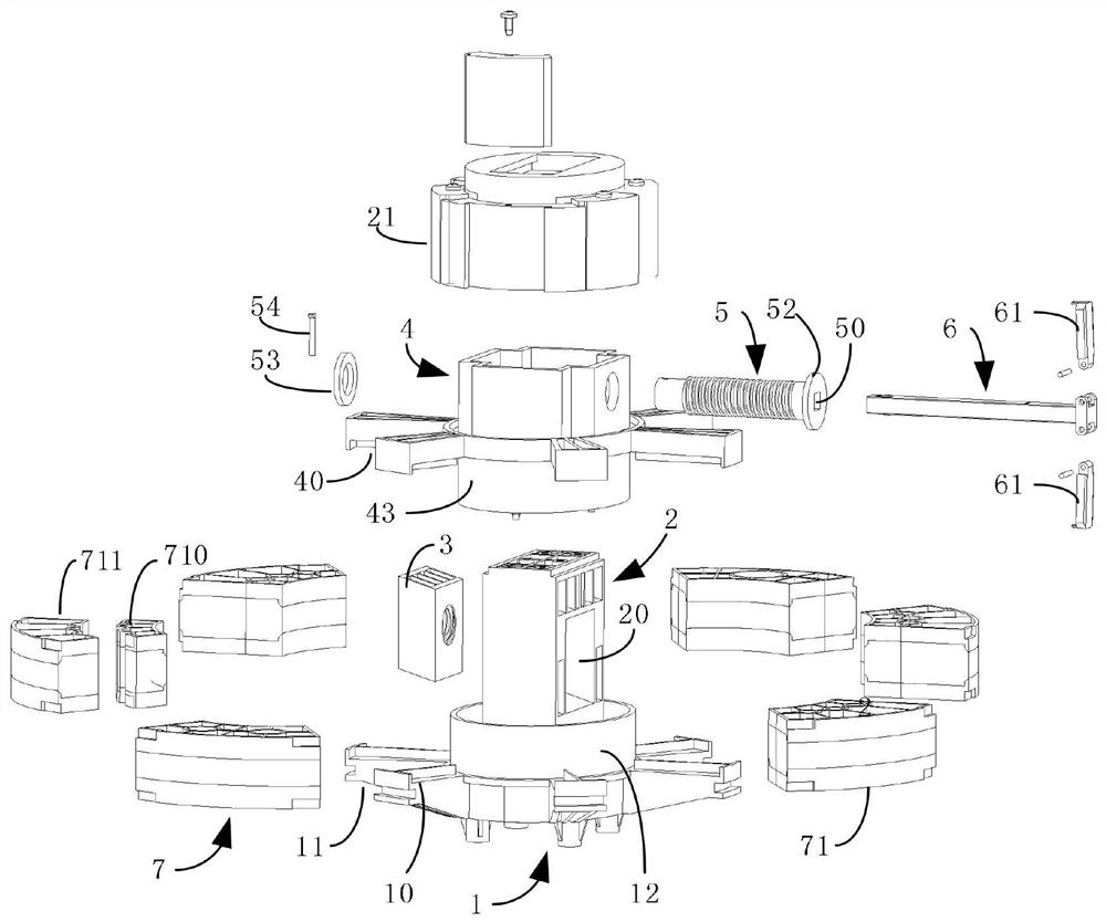
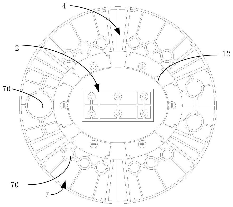
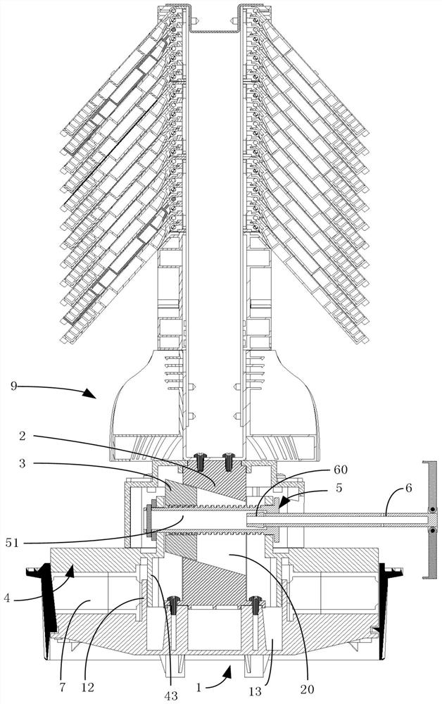
[0053] see figure 1 and figure 2As shown, the first embodiment of the present invention provides an extrusion device for sealing an optical cable splice closure, which includes a base 1, a column 2, a slider 3, an extrusion structure 4, a rotating shaft 5 and an operating rod 6; the base 1 includes a mounting part (not shown in the figure) and a bearing part 10 arranged internally and externally and connected to each other. The bearing part 10 is provided with a first cable routing channel 11 for the optical cable to pass through from bottom to top at intervals along the circumference of the mounting part. The bearing part The elastic sealing body 7 is carried on the 10, and the elastic sealing body 7 is provided with a plurality of through grooves 70 for optical cables to pass through, and the through grooves 70 are distributed in an oval s...


PUM


Abstract

The invention discloses an extrusion device for sealing an optical cable joint box and an optical cable joint box. The base includes a mounting part and a bearing part. The bearing part is provided with a first cable running channel at intervals along the circumferential direction of the mounting part. The bearing part carries an elastic seal The elastic sealing body is provided with a plurality of elliptical through grooves, the upright column is set on the installation part, and the length direction projected on the installation part is in the same direction as the long axis of the ellipse, and the upright column is provided with inclined track grooves; The block is set in the track groove; the extrusion structure is sleeved on the column, which is provided with the second cable channel; the rotation axis is horizontally installed in the extrusion structure and is located above the second cable channel, and the rotation axis passes through the track groove and Screwed with the slider; the operating rod rotates the rotating shaft, drives the slider to move in the track groove, and drives the rotating shaft to move in the vertical direction relative to the column through the slider, so that the extrusion structure squeezes or loosens the elastic sealing body . The present invention reduces the lateral drop of the cylindrical structure while achieving the cable feeding density of the cylindrical structure.

Description

technical field [0001] The invention relates to the field of communication optical cable joint boxes, in particular to an extrusion device for sealing an optical cable joint box and an optical cable joint box. Background technique [0002] In recent years, with the vigorous development of Internet information technology, people's demand for network bandwidth is getting higher and higher. Hundreds of millions of users are using and accessing the Internet every second, and huge data traffic requires equipment to connect and transmit . Today, with the explosive growth of information and the accelerated pace of life, the requirements for the density of optical fiber connections are constantly increasing, and the equipment installation and operation steps are required to be simplified as much as possible. [0003] At present, the hat-type optical cable splice closures on the market mainly have the following two shapes: [0004] The first type is a cylindrical structure. Since t...

Claims


Application Information

Patent Timeline
Patent Type & Authority Patents(China)
IPC IPC(8): G02B6/44
CPCG02B6/4446
Inventor 程淑玲王军魏文振卢德坤
Owner FENGHUO COMM SCI & TECH CO LTD
Why Eureka
Try Eureka