Electric blind valve
A blind valve, electric technology, applied in the direction of lift valve, valve details, valve device, etc., can solve the problems of easy blocking, sealing and falling of blind valve, and achieve the effect of improving stability and sealing.
- Summary
- Abstract
- Description
- Claims
- Application Information
AI Technical Summary
Problems solved by technology
Method used
Image
Examples
Embodiment 1
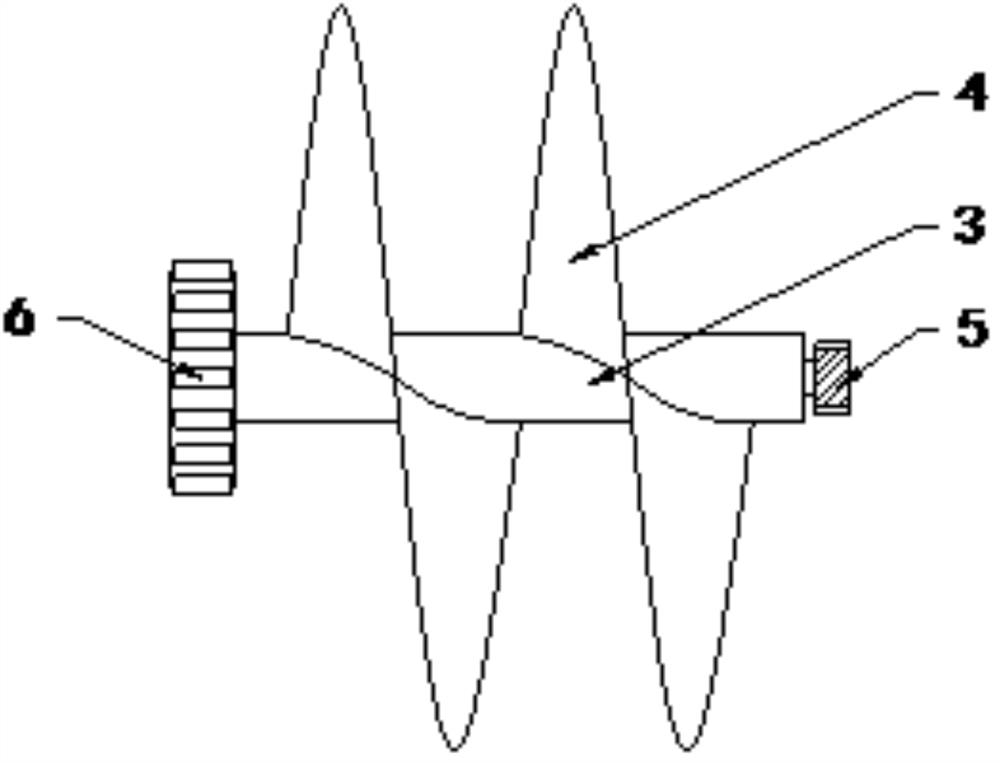
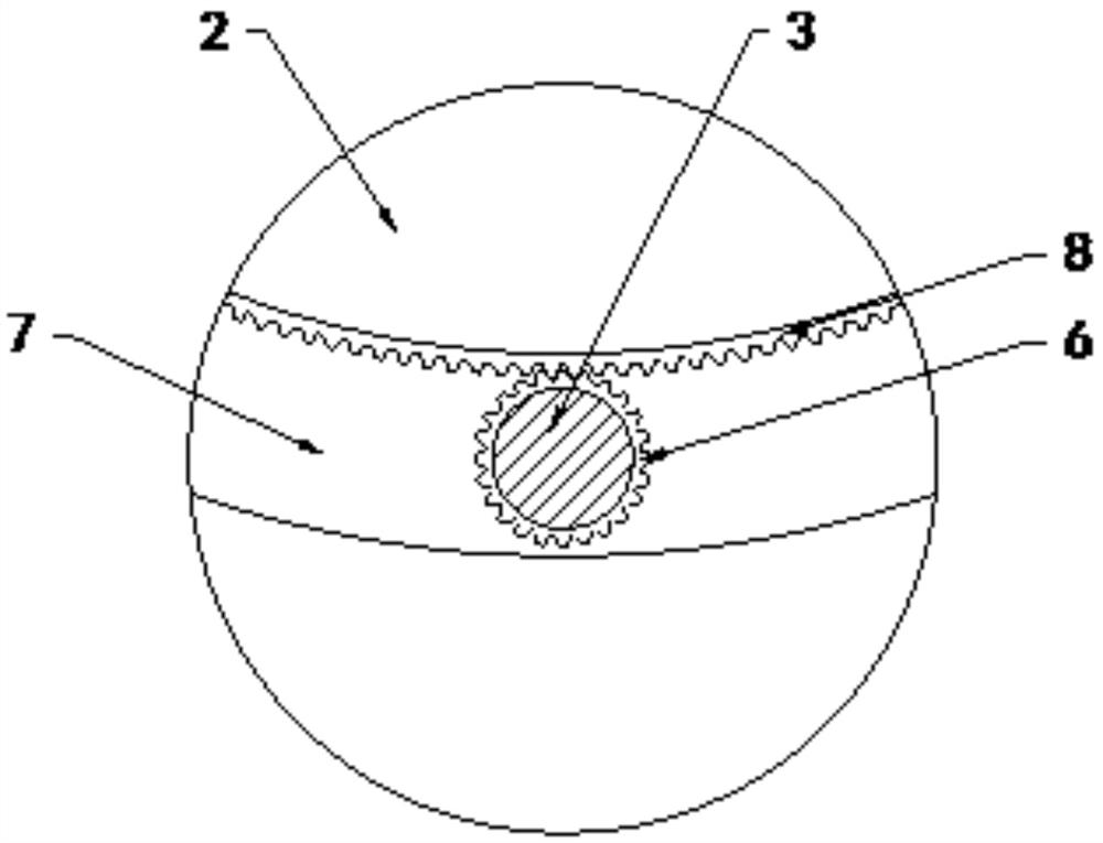
[0034] see figure 1 , figure 2 with image 3 , an electric blind valve, including a valve body 1, a valve plate 2, a driving device 9 and a transmission rod 10, the inside of the valve body 1 is provided with a central shaft 3, the outer wall of the central shaft 3 is fixedly connected with a stirring plate 4, and the central shaft 3 The end away from the support rod 5 is fixedly connected with a gear 6, and the end surface of the valve plate 2 close to the central axis 3 is provided with a groove 7, and the inner upper surface wall of the groove 7 is fixedly connected with a rack 8, and the gear 6 and the rack 8 meshing connection, the gear 6 is driven to rotate through the rack 8, and then the stirring plate 4 is rotated to remove the residual material. The valve plate 2 is located inside the valve body 1, and the driving device 9 is fixedly connected to the outer side of the valve body 1, and The output shaft of the driving device 9 is connected with a transmission rod 1...
Embodiment 2
[0036] see figure 1 , figure 2 , image 3 , Figure 4 with Figure 5 , an electric blind valve, including a valve body 1, a valve plate 2, a driving device 9 and a transmission rod 10, the inside of the valve body 1 is provided with a central shaft 3, the outer wall of the central shaft 3 is fixedly connected with a stirring plate 4, and the central shaft 3 The end away from the support rod 5 is fixedly connected with a gear 6, and the end surface of the valve plate 2 close to the central axis 3 is provided with a groove 7, and the inner upper surface wall of the groove 7 is fixedly connected with a rack 8, and the gear 6 and the rack 8 meshing connection, the gear 6 is driven to rotate through the rack 8, and then the stirring plate 4 is rotated to remove the residual material. The valve plate 2 is located inside the valve body 1, and the driving device 9 is fixedly connected to the outer side of the valve body 1, and The output shaft of the driving device 9 is connected...
PUM
 Abstract
Description
Claims
Application Information
 - R&D
- Intellectual Property
- Life Sciences
- Materials
- Tech Scout
- Unparalleled Data Quality
- Higher Quality Content
- 60% Fewer Hallucinations
Browse by: Latest US Patents, China's latest patents, Technical Efficacy Thesaurus, Application Domain, Technology Topic, Popular Technical Reports.
© 2025 PatSnap. All rights reserved.Legal|Privacy policy|Modern Slavery Act Transparency Statement|Sitemap|About US| Contact US: help@patsnap.com


