


Quick Research
Generate reliable direction feasibility study reports for your R&D in just a few steps.

Technical Q&A
Discover and master advanced knowledge NOW. Basics, ideas, possibilities, all at once.

Find Solutions
As an expert in R&D theories, this can generate solutions to your technical problems instantly.

Evaluate Feasibility
Analyze your overall solution with one click, know your potential R&D risks in advance.

Monitor Landscape
Get weekly tech updates, stay abreast of the latest tech innovations and key insights.
Transferring and conveying system behind mobile crushing station and transferring and conveying method of transferring and conveying system
A mobile crushing and conveying system technology, applied in the direction of conveyors, loading/unloading, conveyor objects, etc., can solve problems such as difficulty in moving and aligning reloading conveying equipment, low reset accuracy, frequent adhesive tape bonding of relocated conveying equipment, etc. Achieve the effect of saving reset installation time, reducing site requirements, and reducing installation site requirements
- Summary
- Abstract
- Description
- Claims
- Application Information
AI Technical Summary
Problems solved by technology
Method used
Image

Examples
Embodiment 1
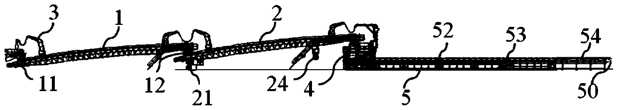
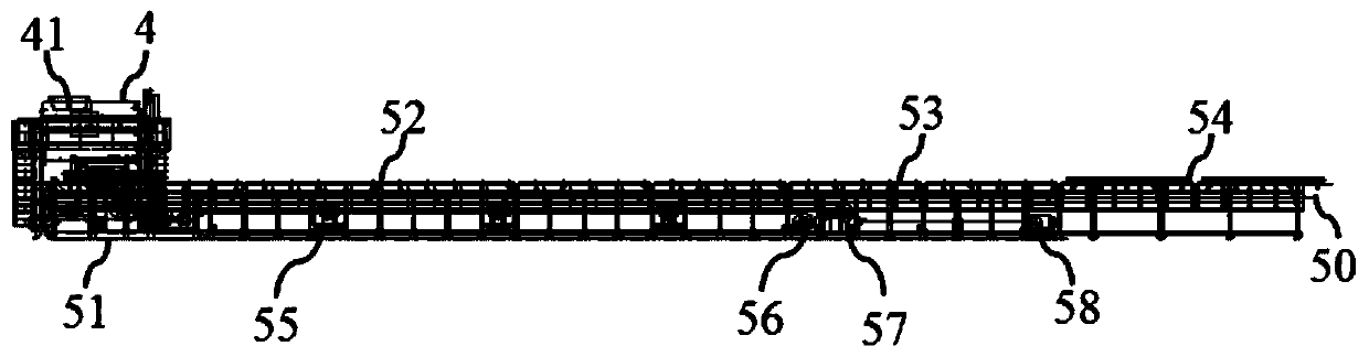
[0034] A kind of transfer conveying system after the mobile crushing station of this embodiment, such as figure 1 As shown, it includes an intelligent reloading device, a mobile unloading funnel 4 and a displacement device 5. The intelligent reloading device is arranged below the discharge port at the tail of the mobile crushing station; above the feed port 41; the mobile discharge funnel 3 is erected and installed on the head of the displacement device 5, and the feed port 31 of the mobile discharge funnel 3 leads to the feed of the displacement device 5 head from above paragraph 51;
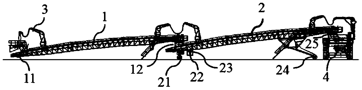
[0035] Such as figure 2 As shown, the intelligent reloading device includes an L1 conveyor 1, the L1 conveyor 1 is connected to the tail of the mobile crushing station through the connecting structure 11 provided at the head, and the tail outlet of the L1 conveyor 1 is set through the turntable I12 Above the head of the L2 conveyor 2, the L1 conveyor 1 can rotate around the L2 conveyor 2 thr...
Embodiment 2
[0039] A mobile crushing station reloading conveying system of this embodiment has the same basic structure as that of Embodiment 1, the differences and improvements are as follows: figure 2 As shown, the turntable I12 is a hollow cylindrical structure, and can be flexibly connected above the feeding port 12 at the head of the L2 conveyor 2, so that the gravel can be discharged into the In the feeding port above the head of the L2 conveyor 2, the reloading and conveying of gravel is realized; the tail of the L2 conveyor 2 is also provided with a turntable II 25, and the turntable II 25 is a hollow cylindrical structure, and can be adapted to be flexibly connected on the move Above the feed port 41 of the discharge funnel 4; when the intelligent reloading device moves, the turntable II 25 is in contact with the feed port 41 of the mobile discharge funnel 4, so that the L2 conveyor 2 can rotate around the mobile discharge funnel 4, In this way, when the intelligent reloading de...
Embodiment 3
[0041] A mobile crushing station reloading conveying system of this embodiment has the same basic structure as that of Embodiment 2, the differences and improvements are as follows: figure 2 As shown, the L2 conveyor 2 is provided with a hydraulic system 23, which is used to control the lifting of the lifting wheel set 24. When the intelligent reloading device is working, the lifting wheel set 24 below the L2 conveyor 2 is lowered to contact with the ground. The discharge port at the tail of the L2 conveyor 2 is lifted to the top of the feed port 41 of the mobile discharge funnel 4 to realize the next step of gravel conveying; The above-mentioned turntable II 25 is in contact with the mobile discharge funnel 4, so that the L2 conveyor 2 can rotate around the mobile discharge funnel 4, thereby ensuring that the transfer device can be transferred without dismantling, saving equipment reset and installation time.
PUM
 Abstract
Description
Claims
Application Information
 - R&D Engineer
- R&D Manager
- IP Professional
- Industry Leading Data Capabilities
- Powerful AI technology
- Patent DNA Extraction
Browse by: Latest US Patents, China's latest patents, Technical Efficacy Thesaurus, Application Domain, Technology Topic, Popular Technical Reports.
© 2024 PatSnap. All rights reserved.Legal|Privacy policy|Modern Slavery Act Transparency Statement|Sitemap|About US| Contact US: help@patsnap.com