Mobile wire coil

A wire reel and frame technology, applied in the field of mobile wire reels, can solve the problems of heavy weight, time-consuming and laborious, knotted wires, etc.

Inactive Publication Date: 2020-03-31
HAIBEI POWER SUPPLY COMPANY STATE GRID QINGHAI ELECTRIC POWER +2
View PDF8 Cites 0 Cited by
  • Summary
  • Abstract
  • Description
  • Claims
  • Application Information

AI Technical Summary

Problems solved by technology

[0002] In the construction and maintenance of transmission lines, it is often necessary to lay out the wires on site, or to coil and organize the used wires. Due to the long rope and heavy weight, it is easy for the staff to lay out or take up the wires on the ground. Phenomena such as knotting and wire bondi

Method used


Image

  • Mobile wire coil
  • Mobile wire coil
  • Mobile wire coil

Examples


Embodiment 1

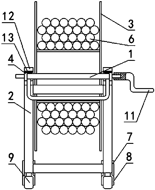
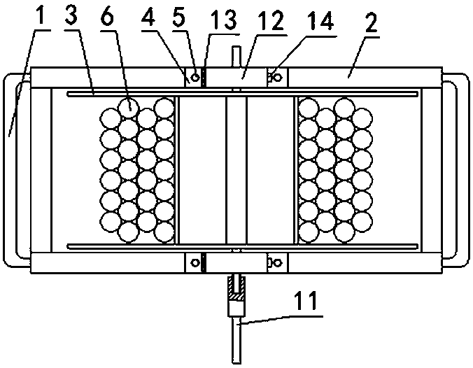
[0016] Example 1 as Figure 1-5 As shown, a mobile reel includes a frame (2), a reel (3), a bearing seat (4), a wheel seat (7), a walking wheel (9), a crank handle (11), and the frame (2) is a rectangular frame, and its front and rear ends are equipped with pull rods (1). Two wheel bases (7) are fixedly connected to the front end of the bottom of the frame (2), and the bottom of the wheel base (7) is movably connected to movable wheels. frame (8), the movable wheel frame (8) is U-shaped, and the middle of the U-shape is sleeved with a walking wheel (9) through a shaft, and the rear end of the bottom of the frame (2) is provided with two fixed wheel frames (10), The fixed wheel frame (10) is sleeved with traveling wheels (9), and the two sides of the upper part of the frame (2) are fixedly connected with bearing seats (4) by bolts (5), and the upper part of the bearing seat (4) is a semi-circular ring , the upper end of the bearing seat (4) is connected with the upper cover (1...

Embodiment 2

[0019] Example 2 as Figure 1-5 As shown, a mobile reel includes a frame (2), a reel (3), a bearing seat (4), a wheel seat (7), a walking wheel (9), a crank handle (11), and the frame (2) is a rectangular frame, and its front and rear ends are equipped with pull rods (1). Two wheel bases (7) are fixedly connected to the front end of the bottom of the frame (2), and the bottom of the wheel base (7) is movably connected to movable wheels. frame (8), the movable wheel frame (8) is U-shaped, and the middle of the U-shape is sleeved with a walking wheel (9) through a shaft, and the rear end of the bottom of the frame (2) is provided with two fixed wheel frames (10), The fixed wheel frame (10) is sleeved with traveling wheels (9), and the two sides of the upper part of the frame (2) are fixedly connected with bearing seats (4) by bolts (5), and the upper part of the bearing seat (4) is a semi-circular ring , the upper end of the bearing seat (4) is connected with the upper cover (1...


PUM


Abstract

The invention discloses a mobile wire coil and relates to the technical field of coiling devices. The mobile wire coil is structurally characterized in that a rack is a rectangular frame, pull rods are arranged on the front end and the back end of the rack, two wheel bases are fixedly connected to the front end of the bottom, the bottoms of the wheel bases are movably connected with movable wheelframes, the movable wheel frames are sleeved with walking wheels, two fixed wheel frames are arranged on the rear end of the bottom of the rack, and are sleeved with walking wheels, bearing pedestalsare fixedly connected to the two sides of the upper portion of the rack through bolts, an upper cover is connected to one end of the upper portion of each bearing pedestal, inner rings are arranged onthe two ends of a wire coil shaft, spokes are welded to the outer circles of the inner rings, the other ends of the spokes are connected with outer rings, shaft heads are welded to two ends of the wire coil shaft, the shaft heads are in fit connection with bearings, one end is connected with a rocking handle, and the two outer rings are fixedly connected through a connecting rod. The mobile wirecoil has the beneficial effects that according to the mobile wire coil, a wire can be conveniently wound, dismounting and mounting of the wire coil are convenient, transport, loading and unloading arerapid and convenient, storage in a storehouse is in order, space is not occupied, payoff and take up save time and labor, and manpower is reduced.

Description

technical field [0001] The invention relates to the technical field of wire coiling devices, in particular to a moving wire coil. Background technique [0002] In the construction and maintenance of transmission lines, it is often necessary to lay out the wires on site, or to coil and organize the used wires. Due to the long rope and heavy weight, it is easy for the staff to lay out or take up the wires on the ground. Phenomena such as knotting and wire bonding to soil are labor-intensive and labor-intensive to deal with. It often requires the cooperation of multiple people to organize them. Moreover, the traditional cables are placed in a mess in the warehouse, and loading and unloading is manual, which is time-consuming and laborious. Contents of the invention [0003] Aiming at the deficiencies of the above-mentioned prior art, the present invention provides a mobile reel, which is characterized in that it includes a frame (2), a reel (3), a bearing seat (4), a wheel se...

Claims


Application Information

Patent Timeline
IPC IPC(8): B65H75/38B65H75/44
CPCB65H75/38B65H75/44
Inventor 王欢范玉亮李彦业刘一帆汪世栋王身徐浩峰杨明明陈颖龙
Owner HAIBEI POWER SUPPLY COMPANY STATE GRID QINGHAI ELECTRIC POWER
Why Eureka
Try Eureka