A rotor winding device for motor processing

A winding device and rotor technology, applied in the direction of electromechanical devices, manufacturing motor generators, electrical components, etc., can solve the problem of inconvenient fixed installation and disassembly of the winding mechanism, achieve convenient installation and disassembly work, and increase the overall connection support strength , the effect of increasing stability

Active Publication Date: 2021-03-26
SHANGHAI FINEPOWER TECH
View PDF5 Cites 0 Cited by
  • Summary
  • Abstract
  • Description
  • Claims
  • Application Information

AI Technical Summary

Problems solved by technology

There are some deficiencies in the above patents: it is inconvenient to fix and disassemble the winding mechanism

Method used


Image

  • A rotor winding device for motor processing
  • A rotor winding device for motor processing
  • A rotor winding device for motor processing

Examples


Embodiment 1

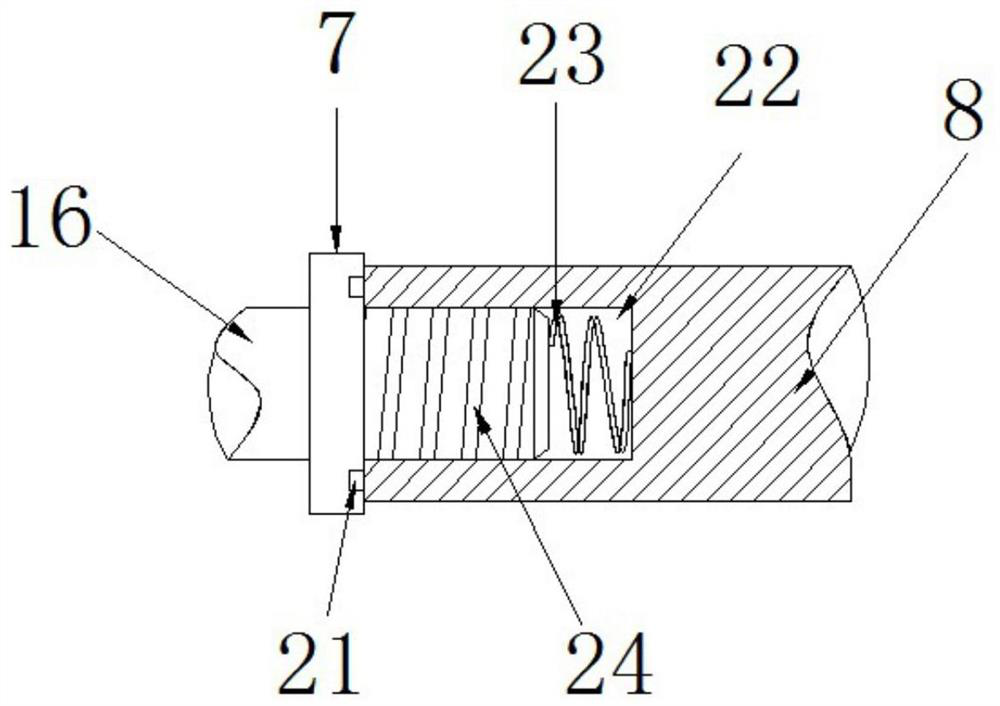
[0025] refer to figure 1 and figure 2 , a rotor winding device for motor processing, including a base 1, a boss 6 is fixed on the left side of the top outer wall of the base 1, a rotating shaft 16 is rotatably inserted on the boss 6, and one end of the rotating shaft 16 is connected with a drive Mechanism, the other end of the rotating shaft 16 is fixed with a screw rod 24, the joint between the screw rod 24 and the rotating shaft 16 is fixed with a limit ring 7, the screw rod 24 is fixed with a winding rod 8, and one end of the winding rod 8 has an insertion slot 22, and the winding rod 8 is threadedly socketed on the screw rod 24 through the insertion slot 22, and a compression spring 23 is placed in the insertion slot 22. A protruding ring 21 is fixed on the outer wall of the winding rod 8 close to the limit ring 7, and the protruding ring 21 is embedded in the In the annular groove provided on the limit ring 7 , a fixed ring 9 and a clamping ring 10 are fixedly sleeved o...

Embodiment 2

[0029] refer to image 3 , a rotor winding device for motor processing. The difference between this embodiment and Embodiment 1 is that a guide block 26 is fixed at one end of the crimping rod 13, and the outer wall of one side of the boss 6 is provided with a guide block 26 to form a sliding Cooperating guide groove 25.

[0030] The working principle of this embodiment: through the setting of the guide block 26, the guide groove 25 can cooperate with the guide groove 25 to play a position-limiting guiding role for the crimping rod 13 moving up and down, thereby increasing the stability of the distance adjustment between the crimping mechanism 12 and the winding rod 8 .


PUM


Abstract

The invention discloses a rotor winding device for motor processing. The device comprises a base, a boss is fixed to the left side of one side of the outer wall of the top of the base. A rotating shaft is rotationally inserted into the boss; one end of the rotating shaft is in transmission connection with a driving mechanism; a screw rod is fixed at the other end of the rotating shaft; a limitingring is fixed at the joint of the screw rod and the rotating shaft; a winding rod is fixed on the screw rod; an inserting groove is formed in one end of the winding rod; the screw rod is sleeved withthe winding rod through the inserting groove in a threaded mode, a compression spring is placed in the inserting groove, a protruding ring is fixed to the outer wall of the side, close to the limitingring, of the winding rod and embedded in an annular groove formed in the limiting ring, the winding rod is fixedly sleeved with a fixing ring and a clamping ring, and a wire pressing mechanism is arranged below the winding rod. The winding rod can be conveniently mounted and dismounted, the overall connecting and supporting strength of the connecting position of the winding rod can be improved, and the structural stability is improved.

Description

technical field [0001] The invention relates to the technical field of motor rotor winding equipment, in particular to a rotor winding device used for motor processing. Background technique [0002] When producing the motor rotor, there is a process of winding the enameled wire into the groove of the rotor. Traditionally, the winding of the ordinary motor rotor must be produced by manual winding, and the production efficiency is low. [0003] After searching, the Chinese patent publication number is CN208094411U, which discloses an automatic winding device for motor rotor coils, including a control board, a chassis, a drive motor, a coupling, a locker, a storage tray, a transmission shaft, and a winding frame , the first wire passing groove, the horizontal groove, the winding groove, the winding bearing, the second wire passing groove, the crimping mechanism, the bushing, the gasket, the fastening bolt, the moving wheel and the fixed plate, and the top of the cabinet passes ...

Claims


Application Information

Patent Timeline
Patent Type & Authority Patents(China)
IPC IPC(8): H02K15/09
CPCH02K15/09
Inventor 谢剑
Owner SHANGHAI FINEPOWER TECH
Why Eureka
Try Eureka