Eureka AIR delivers breakthrough ideas for toughest innovation challenges, trusted by R&D personnel around the world.

Multi-frequency antenna and communication device

A multi-frequency antenna, high-frequency technology, applied in the field of communication, can solve problems such as signal interference

Active Publication Date: 2020-03-27
SHANGHAI HUAWEI TECH CO LTD
View PDF6 Cites 8 Cited by
  • Summary
  • Abstract
  • Description
  • Claims
  • Application Information

AI Technical Summary

Problems solved by technology

[0004] When the low-frequency unit is working, the above-mentioned equivalent monopole antenna will generate a low-frequency induced current under the influence of the electromagnetic wave of the low-frequency unit. The low-frequency induced current causes the monopole antenna to radiate low-frequency electromagnetic waves outward, and the electromagnetic wave The frequency is approximately equal to the frequency of the electromagnetic wave radiated by the low-frequency unit, causing interference to the signal radiated and transmitted by the low-frequency unit

Method used


Image

  • Multi-frequency antenna and communication device
  • Multi-frequency antenna and communication device
  • Multi-frequency antenna and communication device

Examples


Embodiment Construction

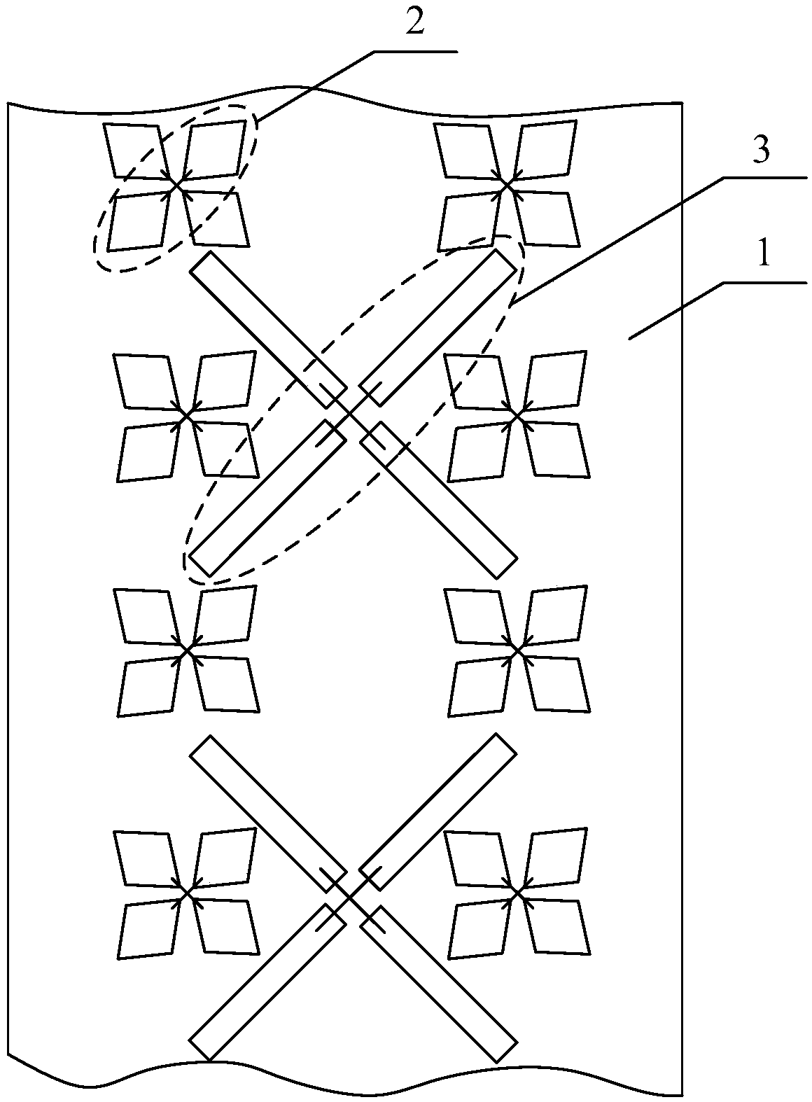
[0053] An embodiment of the present invention provides a multi-frequency antenna, which is an antenna with multiple working frequency bands, such as figure 1 and refer to figure 2 As shown, the multi-frequency antenna includes a reflector 1, at least one high-frequency unit 2 and at least one low-frequency unit 3, such as image 3 As shown, each high-frequency unit 2 includes a balun structure 21, a coupling structure 22 and a radiation arm structure 23, the balun structure 21 includes two balun substructures 211, the coupling structure 22 includes two coupling substructures 221, and the radiation arm The structure 23 includes two radiating arms 231, wherein: at least one high-frequency unit 2 and at least one low-frequency unit 3 are mounted on the reflector 1; in each high-frequency unit 2, each coupling substructure 221 is respectively connected with a balun The substructure 211 and a radiation arm 231 are electrically connected; the coupling substructure 221 is used for ...


PUM


Abstract

The embodiment of the invention discloses a multi-frequency antenna and a communication device, and belongs to the technical field of communication. The multi-frequency antenna comprises a reflectingplate, at least one high-frequency unit and at least one low-frequency unit, wherein each high-frequency unit comprises a balun structure, a coupling structure and a radiation arm structure, the balunstructure comprises two balun substructures, the coupling structure comprises two coupling substructures, the radiation arm structure comprises two radiation arms, and the high-frequency unit and thelow-frequency unit are installed on the reflecting plate; each coupling sub-structure is electrically connected with one balun sub-structure and one radiation arm; and the coupling substructure is used for transmitting signals of which the frequency is higher than a preset threshold value and blocking signals of which the frequency is lower than the preset threshold value. By the adoption of theantenna, due to the existence of the coupling structure, the frequency of electromagnetic waves radiated outwards by the equivalent monopole antenna is higher than the preset threshold value, the working frequency band of the low-frequency unit is avoided, and then the equivalent monopole antenna cannot interfere with signals radiated and transmitted by the low-frequency unit.

Description

technical field [0001] The present application relates to the field of communication technologies, and in particular, to a multi-frequency antenna and a communication device. Background technique [0002] A multi-frequency antenna is an antenna with multiple operating frequency bands, including a reflector, at least one high-frequency unit and at least one low-frequency unit, wherein each high-frequency unit includes a balun structure and a radiation arm structure. The radiation arm structure is a symmetrical arrangement of two radiation arms. The ends of the two radiation arms that are close to each other are electrically connected to the balun structure. The radiation arm structure is used to radiate electromagnetic waves outward; the balun structure (balance-unbalance, balun) It is the transliteration of the abbreviation of "balanced-unbalanced converter" in English, and is a device used for signal connection to the radiating arm structure of the antenna and the cable. A...

Claims


Application Information

Patent Timeline
Patent Type & Authority Applications(China)
IPC IPC(8): H01Q1/36H01Q5/50H01Q15/14
CPCH01Q1/36H01Q15/14H01Q5/50H01Q5/42H01Q5/48H01Q5/307H01Q19/108H01Q21/26H01Q5/45
Inventor 白雪王乃彪谢国庆肖伟宏
Owner SHANGHAI HUAWEI TECH CO LTD
Why Eureka
Eureka Blog
Learn More