Triaxial accelerometer device for tunnel magnetic resistance detection

A technology of tunnel magnetoresistance and axis acceleration, applied in the field of micro-inertial navigation, can solve problems such as interference, achieve the effect of solving the problem of centrifugal force and improving detection accuracy

Pending Publication Date: 2020-03-27
ZHONGBEI UNIV
View PDF1 Cites 6 Cited by
  • Summary
  • Abstract
  • Description
  • Claims
  • Application Information

AI Technical Summary

Problems solved by technology

The advantages of the present invention lie in the following two points: 1. The driving beam structure designed this time is an orthogonal beam structure, while the reference file is a straight beam. In contrast, the beam structure designed this time is not easy to be damaged due to processing, and can be obtained High yield, and at the same time, by effectively designing the aspect ratio and gap of the beam, the best accelerometer performance is obtained; 2. This time, the tunnel magnetoresistance effect, which is more sensitive to the magnetic field, is used for detection, while the reference document uses The detection of the giant magnetoresistance effect will be far less sensitive to the magnetic field than the tunnel magnetoresistance effect. Therefore, the sensitivity of the accelerometer will be greatly improved by using the tunnel magnetoresistance effect for acceleration detection. The research group applied for the " A tunnel magneto-resistance non-resonant three-axis MEMS gyro" (application number 2017106955645), which uses a structure that can measure both angular rate and acceleration. When the magnetoresistive element detects the change of the magnetic field, it produces great interference, and there is still no product that can solve this problem

Method used


Image

  • Triaxial accelerometer device for tunnel magnetic resistance detection
  • Triaxial accelerometer device for tunnel magnetic resistance detection
  • Triaxial accelerometer device for tunnel magnetic resistance detection

Examples


Embodiment Construction

[0061] Embodiments of the present invention are described in detail below, examples of which are shown in the drawings, wherein the same or similar reference numerals designate the same or similar elements or elements having the same or similar functions throughout. The embodiments described below by referring to the figures are exemplary only for explaining the present invention and should not be construed as limiting the present invention.

[0062] In the description of the present invention, it should be understood that the orientations or positional relationships indicated by the terms "center", "upper", "lower", "front", "rear", "left", "right" etc. are based on the attached The orientation or positional relationship shown in the figure is only for the convenience of describing the present invention and simplifying the description, and does not indicate or imply that the referred combination or element must have a specific orientation, be constructed and operated in a spec...


PUM


Abstract

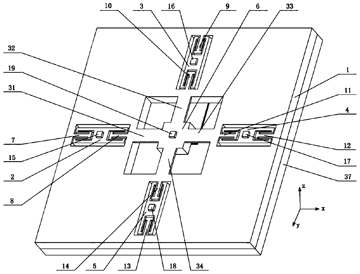
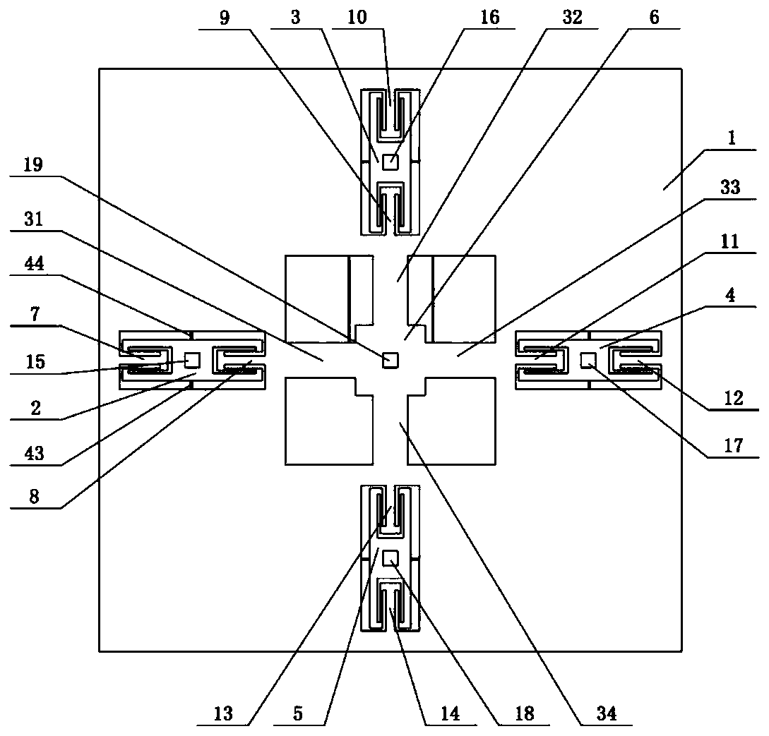
The invention belongs to the technical field of micro inertial navigation, and particularly relates to a triaxial accelerometer device for tunnel magnetoresistance detection. The triaxial accelerometer device for tunnel magnetic resistance detection is composed of a bonding substrate, a support frame, a sensitive mass block, a detection beam, a connecting block, a cantilever beam, a detection magnet, a tunnel magnetoresistive element and a signal line. The sensitive mass block, the detection composite beam and the cantilever beam are arranged on the support frame; a detection magnet is arranged on a sensitive mass block, the sensitive mass block and detection combination beams located on the two sides of the sensitive mass block jointly form a rectangular detection structure, the rectangular detection structure is located in the axis direction of the detection direction of the overall structure of the triaxial accelerometer device, and high-precision acceleration detection is achieved.The structure of the device has high sensitivity to weak magnetic field change, and the device is reasonable and simple in design, easy in monolithic integration and suitable for microminiaturization.

Description

technical field [0001] The invention belongs to the technical field of micro-inertial navigation, and in particular relates to a three-axis accelerometer device for tunnel magnetoresistance detection. Background technique [0002] Micromechanical accelerometer is a sensor used to measure acceleration and is one of the core devices of inertial technology. It plays an important role in modern industrial control, aerospace, national defense, consumer electronics and other fields, and has always been recognized by the world's micro inertial navigation technology field. highly valued. [0003] At present, the measurement of the acceleration by the micromachined accelerometer is completed by the force-electric conversion of the detection device. Its sensitivity and resolution are very important. Due to the miniaturization and integration of the accelerometer, the sensitive area of ​​the detection is reduced accordingly. Therefore, the detection sensitivity, resolution and other i...

Claims


Application Information

Patent Timeline
IPC IPC(8): G01P15/105
CPCG01P15/105
Inventor 张瑞秦世洋李孟委金丽
Owner ZHONGBEI UNIV
Why Eureka
Try Eureka