
Device and method for obtaining micro tissue blocks at high throughput

A tissue block, high-throughput technology, applied in sampling devices and other directions, can solve problems such as large errors and complicated operations, and achieve the effects of high precision, simple sampling, and high-throughput automatic sampling

Active Publication Date: 2020-03-27
HUAZHONG UNIV OF SCI & TECH
View PDF8 Cites 0 Cited by
  • Summary
  • Abstract
  • Description
  • Claims
  • Application Information

AI Technical Summary

Problems solved by technology

[0004] The purpose of the present invention is to provide a high-throughput device and method for obtaining micro-tissue blocks, so as to solve the problems in the prior art that the sampling operation of large tissues at multiple positions is complicated and the error is large

Method used


Image

  • Device and method for obtaining micro tissue blocks at high throughput
  • Device and method for obtaining micro tissue blocks at high throughput
  • Device and method for obtaining micro tissue blocks at high throughput

Examples


Embodiment 1

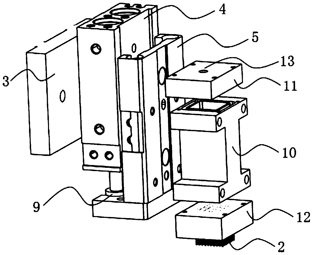
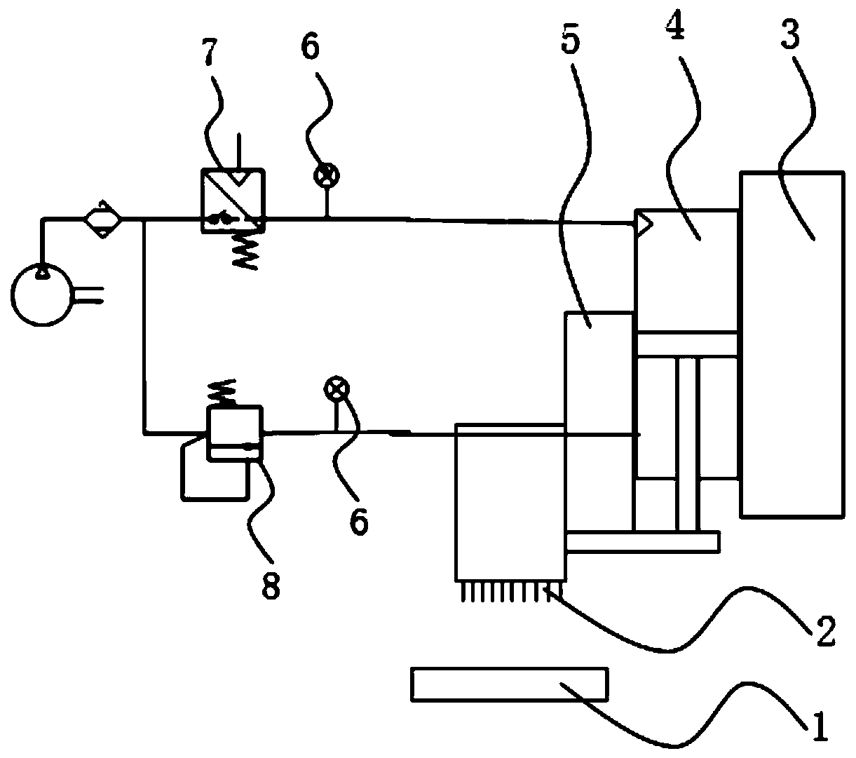
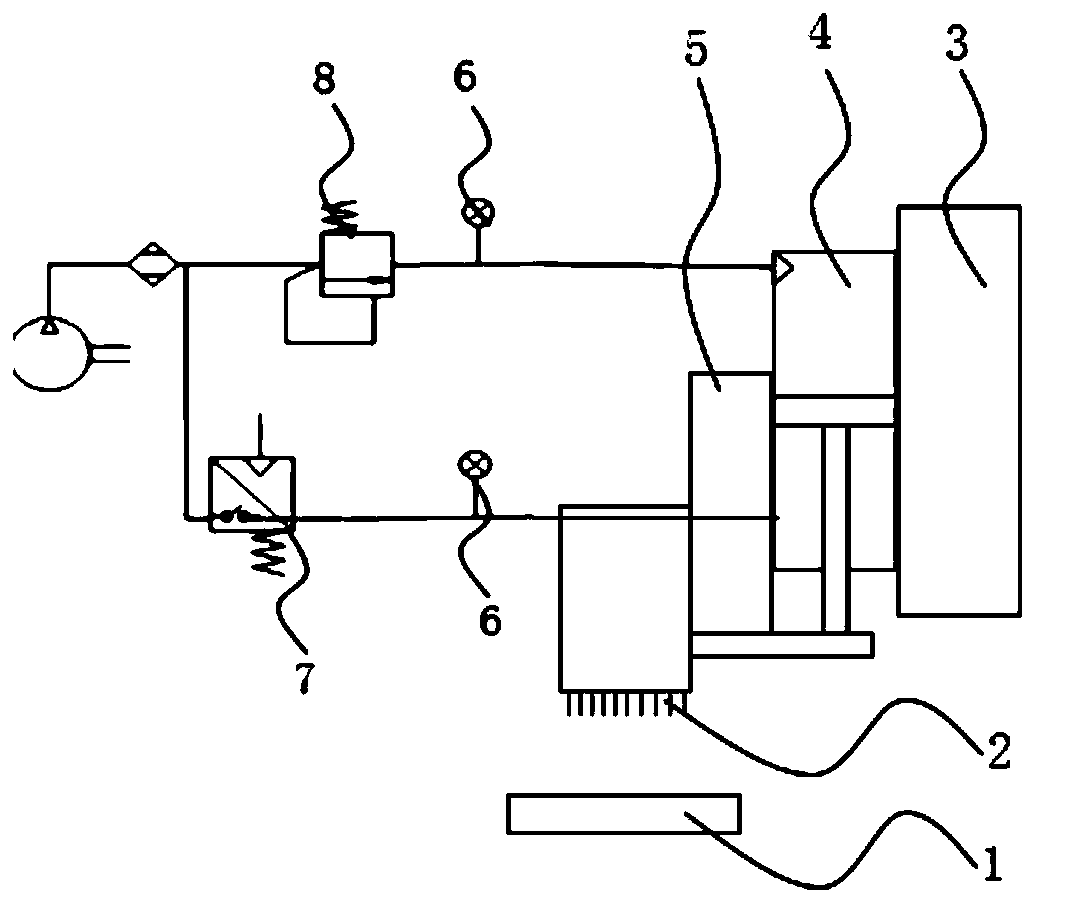
[0042] refer to figure 1 , is a high-throughput device for obtaining micro-tissue blocks disclosed in this embodiment, including a sample table 1, sampling needles 2 distributed in an array, a flexible component that drives the sampling needle 2 to advance or retract, and a three-dimensional structure that drives the flexible component to move longitudinally. Translation stage 3.

[0043] The flexible component includes a cylinder 4 and a positioning part. The cylinder 4 is fixed on the side wall of the three-dimensional translation platform 3. The three-dimensional translation platform 3 drives the cylinder 4 to move longitudinally. The cylinder 4 is used to drive the sampling needle 2 to advance or retract.

[0044] The positioning part is the sliding table 5 that is clamped on the side wall of the cylinder 4, which is used to limit the rotation of the piston rod of the cylinder 4 when it is retracted. 5 realizes linear motion by clamping with the limit guide rail, the bott...

Embodiment 2

[0052] A high-throughput method for obtaining micro-tissue blocks disclosed in this embodiment includes the following steps:

[0053] refer to Figure 4 , take an array base plate, insert the sampling needles in an array distribution on the array base plate, and then use soldering glue to fix the sampling pins on the array base plate, the specific operation is as follows:

[0054] S101, take two mutually perpendicular optical glasses 14, U-shaped auxiliary orifice plate; the U-shaped auxiliary orifice plate includes a flat plate 15 and threaded pillars 16 located on both sides of the flat plate 15 and screwed into the flat plate 15, and place the flat plate 15 in it An upper surface of optical glass 14.

[0055] S102, rotate the threaded pillars 16 on both sides of the flat plate 15 to make the two threaded pillars 16 equal in height, take a pinhole array bottom plate 12, and place it on the upper surface of the two threaded pillars 16, so that the array bottom plate 12 is pa...


PUM


Abstract

The invention provides a device and a method for obtaining micro tissue blocks at high throughput, and relates to the technical field of slice sampling. The device comprises a sample table, sampling needles distributed in an array, a flexible assembly for driving the sampling needles to advance or retract, and a three-dimensional translation table. The flexible assembly comprises an air cylinder and a positioning part used for limiting rotation of a piston rod of the air cylinder. The sampling needles are distributed in an array manner, and high-flux sampling can be completed at a time. The flexible assembly drives the sampling needle to flexibly advance for sampling, so that the acting force between the sampling needle and the tissue can be well adjusted. The positioning part ensures thatthe sampling needle does not rotate along with the piston rod of the air cylinder in the whole sampling process, so that the relative position between the sampling needle array and the sample is prevented from deflecting, the success of repeated sampling of similar samples can be ensured, and the purpose of protecting the sampling needle can be achieved.

Description

technical field [0001] The invention relates to the technical field of slice sampling, in particular to a device and method for obtaining micro-tissue blocks with high throughput. Background technique [0002] In order to obtain the spatial and omics information of biological tissues at the same time, it is necessary to image tissue slices, accurately locate the location of the target tissue area through the imaging results, and then use a sampling device to obtain the tissue in this area for subsequent omics analysis. [0003] In the prior art, sampling needles or laser cutting technology are usually used to sample tissue sections. For large tissue sections, when it is desired to perform multi-position interval sampling for comparative analysis of differences, sampling through sampling needles requires multiple times. Repeated operations, and the sampling interval is not easy to control, the operation is complicated, and the error is large; the laser cutting technology is e...

Claims


Application Information

Patent Timeline
Patent Type & Authority Applications(China)
IPC IPC(8): G01N1/04
CPCG01N1/04
Inventor 骆清铭袁菁韩雨彤龚辉
Owner HUAZHONG UNIV OF SCI & TECH
Learn More