Pantograph device for bullet train electrical system

A technology for electrical systems and pantographs, applied to electric vehicles, current collectors, vehicle components, etc., can solve the problems of affecting the contact effect between the skateboard and the power grid, inconvenient control, cumbersome operation, etc., so as to avoid poor contact and facilitate Controlling and ensuring the effect of rationality

Pending Publication Date: 2021-05-14
HUNAN UNIV OF TECH
View PDF0 Cites 0 Cited by
  • Summary
  • Abstract
  • Description
  • Claims
  • Application Information

AI Technical Summary

Problems solved by technology

[0003] The pantograph is mainly composed of a support device and a slide plate. In order to ensure that the slide plate can always be in contact with the power grid under the ups and downs of the train, the slide plate and the support device are elastically connected. However, the traditional pantograph only connects the slide plate and the The support devices are designed to be elastically connected, and the support devices are stable and fixed connections. Therefore, after a long period of use, the elastic potential energy between the skateboard and the support device will change, which will affect the contact effect between the skateboard and the grid, and it is easy to contact Unfavorable phenomenon, and the traditional pantograph can only adjust the force between the skateboard and the grid by adjusting the height of the skateboard, which is cumbersome to operate and not easy to control

Method used


Image

  • Pantograph device for bullet train electrical system
  • Pantograph device for bullet train electrical system
  • Pantograph device for bullet train electrical system

Examples


Embodiment Construction

[0023] The following will clearly and completely describe the technical solutions in the embodiments of the present invention with reference to the accompanying drawings in the embodiments of the present invention. Obviously, the described embodiments are only some, not all, embodiments of the present invention. Based on the embodiments of the present invention, all other embodiments obtained by persons of ordinary skill in the art without making creative efforts belong to the protection scope of the present invention.

[0024] The embodiment of the pantograph device for the motor vehicle electrical system is as follows:

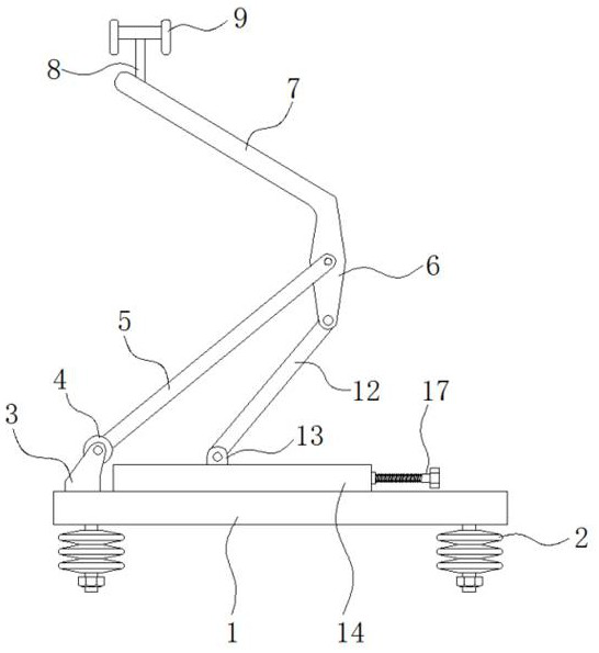
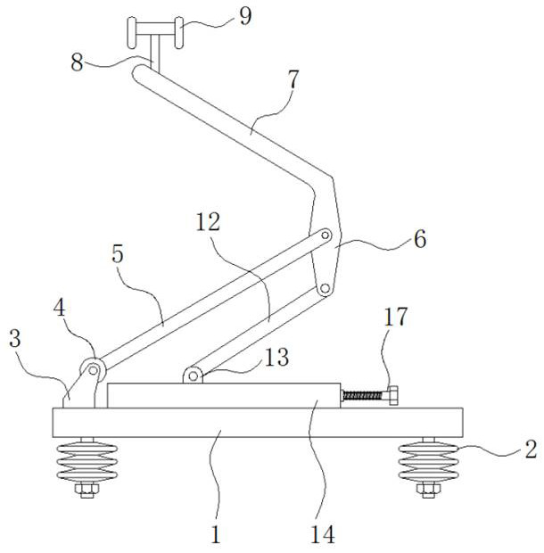
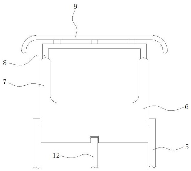
[0025] see Figure 1-5 , a pantograph device for the electrical system of a motor vehicle, including a base 1, a terminal block 2, a triangular plate 3, a rotating cylinder 4, a first rotating rod 5, a rotating plate 6, a supporting rod 7, a connecting rod 8, and a contact plate 9 , the first slider 10, the first spring 11, the second rotating rod 12, the c...


PUM


Abstract

The invention provides a pantograph device for a bullet train electrical system, and relates to the technical field of bullet train electrical systems. The pantograph device for the bullet train electrical system comprises a base, a wire holder is fixedly mounted at the bottom end of the base, triangular plates are fixedly mounted at the top end of the left side of the wire holder, a rotating cylinder is rotationally connected between the triangular plates, a first rotating rod is fixedly mounted on the periphery of the rotating cylinder, a rotating plate is rotationally connected with the other end of the first rotating rod, and a supporting rod is fixedly mounted at the top end of the rotating plate. According to the pantograph device for the bullet train electrical system, when a bullet train fluctuates, it can be guaranteed that a touch panel moves up and down more effectively, effective contact between the touch panel and a power grid can be guaranteed, the phenomenon of poor contact is avoided, the acting force between the touch panel and the power grid can be adjusted more conveniently and rapidly, control is convenient, and the rationality of acting force between the touch panel and the power grid is ensured.

Description

technical field [0001] The invention relates to the technical field of motor vehicle electrical systems, in particular to a pantograph device for motor vehicle electrical systems. Background technique [0002] EMU, the full name of power vehicle, refers to the vehicle equipped with power plant in the rail transit system, and now the power source of the EMU power system is mainly provided by the power grid installed above the track, so in the process of moving the EMU, it needs The power connection device is always in contact with the power grid, and this power connection device installed on the top of the train is collectively called the pantograph. [0003] The pantograph is mainly composed of a support device and a slide plate. In order to ensure that the slide plate can always be in contact with the power grid under the ups and downs of the train, the slide plate and the support device are elastically connected. However, the traditional pantograph only connects the slide ...

Claims


Application Information

Patent Timeline
IPC IPC(8): B60L5/18B60L5/20B60L5/28
CPCB60L5/18B60L5/20B60L5/28
Inventor 刘水长
Owner HUNAN UNIV OF TECH
Why Eureka
Try Eureka