
Low dew point compound dehumidifier

A dehumidifier, low dew point technology, applied in mechanical equipment, heating methods, lighting and heating equipment, etc., can solve the problems of difficult, low dew point dehumidification and high efficiency dehumidification of dehumidifiers, and achieve the effect of regeneration and low air humidity.

Active Publication Date: 2021-02-19
GREE ELECTRIC APPLIANCES INC
View PDF20 Cites 0 Cited by
  • Summary
  • Abstract
  • Description
  • Claims
  • Application Information

AI Technical Summary

Problems solved by technology

[0004] The purpose of the present invention is to provide a low dew point composite dehumidifier, which solves the technical problem that existing dehumidifiers in the prior art are difficult to achieve low dew point dehumidification and high-efficiency dehumidification at the same time

Method used


Image

  • Low dew point compound dehumidifier
  • Low dew point compound dehumidifier
  • Low dew point compound dehumidifier

Examples


Embodiment 1

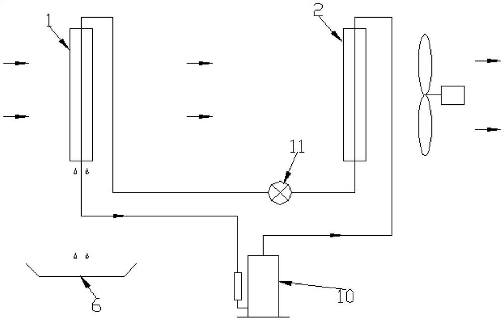
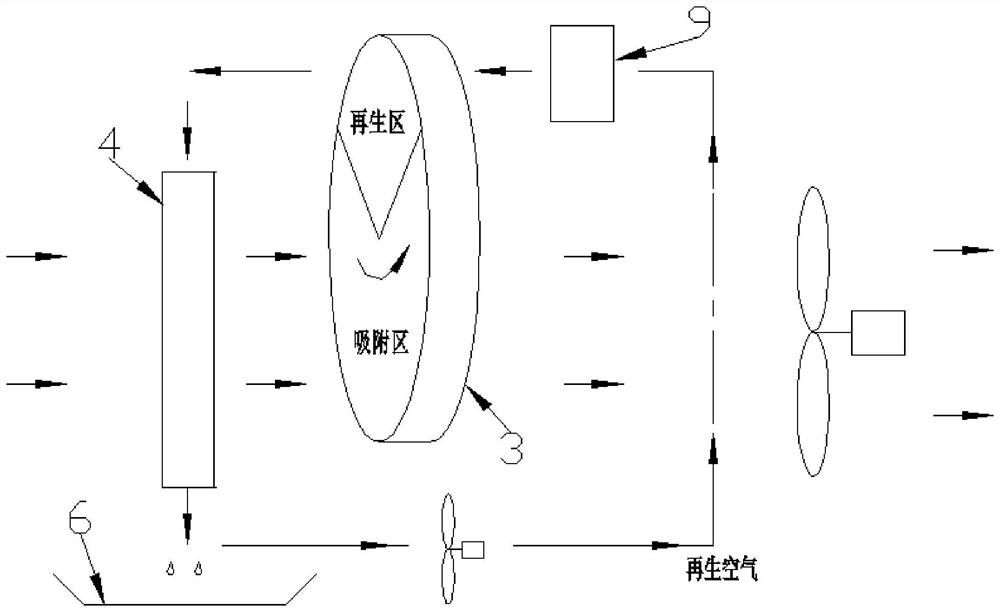
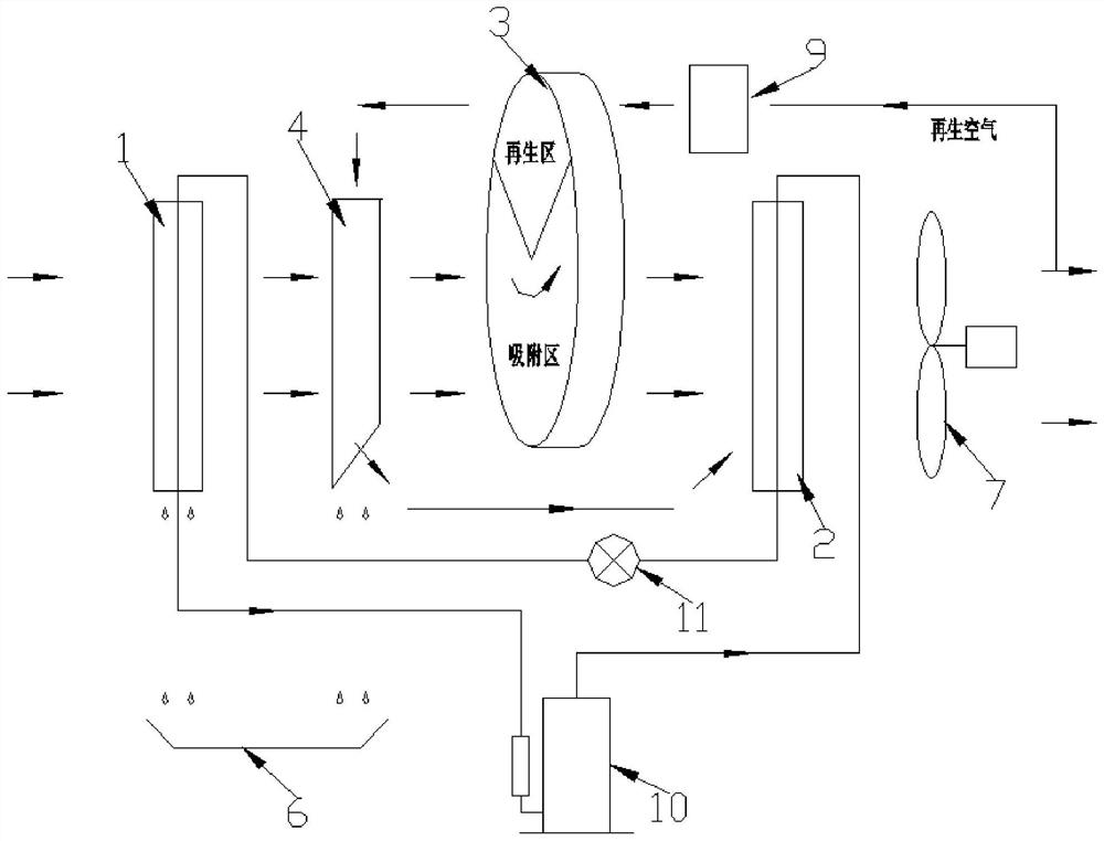
[0034] see image 3 , a low dew point composite dehumidifier, including a dehumidification air channel and a regeneration air channel, wherein the dehumidification air channel is provided with a rotary dehumidification mechanism and a compression refrigeration mechanism, the compression refrigeration mechanism includes an evaporator 1 and a condenser 2, and the rotary dehumidification mechanism Including the dehumidification wheel 3 and the first heat exchanger 4, the air on the dehumidification air duct can pass through the evaporator 1, the first heat exchanger 4, the adsorption area on the dehumidification wheel 3 and the condenser 2 in sequence, and then flow to the atmosphere; after condensation Part of the airflow of the device 2 flows to the condenser 2 after passing through the heater 9, the regeneration zone on the dehumidification wheel 3, and the first heat exchanger 4, and the first fan 7 is located on the air outlet side of the condenser 2.

Embodiment 2

[0036] see Figure 4, a low dew point composite dehumidifier, the difference from Example 1 is that the regeneration air duct is provided with a second heat exchanger 5 for reducing the temperature of the air on the regeneration air duct, and the air passing through the regeneration area of ​​the dehumidification wheel passes through the second heat exchange After the device 5, it flows to the first heat exchanger 4, and the second heat exchanger 5 is used in conjunction with the pre-cooling fan 12.

Embodiment 3

[0038] see Figure 5 , a low dew point composite dehumidifier, the difference from Example 2 is that a second fan 8 is provided on the regeneration air duct, and part of the air flow passing through the condenser 2 flows to the heater 9 through the second fan 8 .

[0039] see Figure 5 , the air passes through the evaporator 1 to cool and condense (first-stage dehumidification), and becomes low-temperature air. The adsorption material in the adsorption area of ​​the wheel absorbs the water (second stage dehumidification), and then the air enters the condenser 2 to be heated, and after passing through the first fan 7, the air with high temperature and high pressure is blown out; at the same time, a part of the blown air is drawn The air returns as regeneration air, and after being further heated by the heater 9, it enters the regeneration zone of the dehumidification rotor 3, and the moisture absorbed by the dehumidification rotor 3 is taken away to form high-temperature and h...


PUM


Abstract

The invention provides a low dew point composite dehumidifier, relates to the technical field of dehumidifiers, and solves the technical problem that existing dehumidifiers in the prior art are difficult to realize low dew point dehumidification and high-efficiency dehumidification at the same time. The device includes a dehumidification air channel and a regeneration air channel, wherein the dehumidification air channel is provided with a wheel dehumidification mechanism and a compression refrigeration mechanism, and the air on the dehumidification air channel can flow to the atmosphere after being dehumidified by the wheel dehumidification mechanism and the compression refrigeration mechanism; the dehumidification air channel The dehumidified air in the dehumidification air duct connected with the regeneration air duct can enter the regeneration air duct, and the air in the regeneration air duct can be discharged to the atmosphere after being dehumidified or can be merged into the dehumidification air duct. The invention is used to improve the efficiency and dehumidification effect of the dehumidifier.

Description

technical field [0001] The invention relates to the technical field of dehumidifiers, in particular to a low dew point composite dehumidifier. Background technique [0002] The existing dehumidifier technology mostly adopts compression refrigeration and condensation technology. The refrigerant evaporates and absorbs heat in the evaporator to cool the air below the dew point, so that the moisture in the air is condensed and collected through the water tray; the compression refrigeration condensation technology The advantage is that the dehumidification capacity is large, but it cannot dehumidify the air with a low dew point. [0003] There are also some dehumidifiers that use the rotary dehumidification technology. After the moisture in the air is absorbed by the rotary wheel, the moisture in the regeneration area is taken away by the high-temperature regeneration air, and the high-temperature and high-humidity regeneration air is cooled and condensed by the air in the heat e...

Claims


Application Information

Patent Timeline
Patent Type & Authority Patents(China)
IPC IPC(8): F24F3/14F24F11/64F24F11/77F24F13/22F24F13/30
CPCF24F3/1405F24F3/1423F24F13/222F24F13/30F24F11/64F24F11/77Y02B30/70
Inventor 何炜姚新祥李江云姚刚
Owner GREE ELECTRIC APPLIANCES INC
Learn More