
Transmission mechanism of spinning motor

A technology of motor drive and spinning, which is applied in the spinning machine, open-end spinning machine, continuous winding spinning machine, etc. It can solve the problems of space shortage and complex tensioning structure of the rotor spinning machine. Achieve the effect of short disassembly time, simple structure and lighten working intensity

Pending Publication Date: 2020-03-27
JINGWEI INTELLIGENT TEXTILE MACHINERY CO LTD
View PDF0 Cites 0 Cited by
  • Summary
  • Abstract
  • Description
  • Claims
  • Application Information

AI Technical Summary

Problems solved by technology

[0003] The technical problem to be solved by the present invention is to provide a spinning motor transmission mechanism to solve the problems of tight space and complex tensioning structure of the rotor spinning machine head

Method used

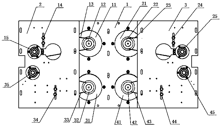
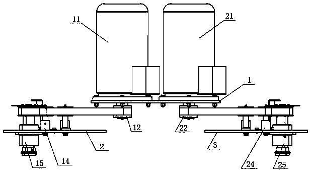
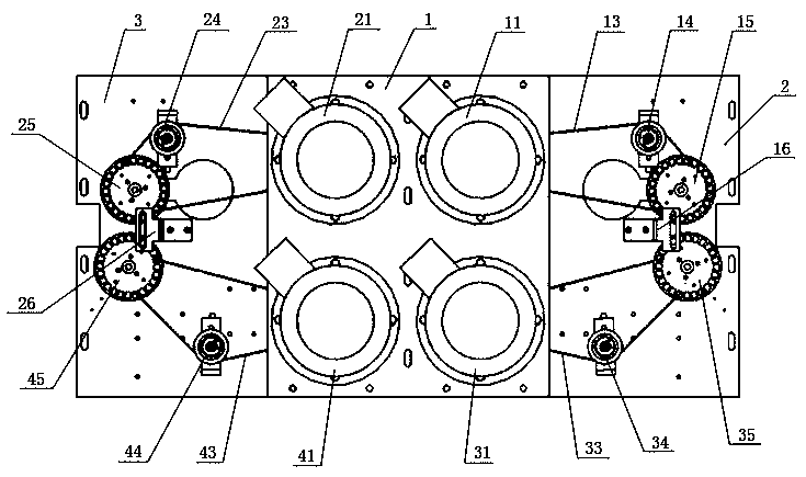

Image

  • Transmission mechanism of spinning motor
  • Transmission mechanism of spinning motor
  • Transmission mechanism of spinning motor

Examples


Embodiment Construction

[0015] It should be noted that, in the case of no conflict, the embodiments in the present application and the features in the embodiments can be combined with each other. The present invention will be described in detail below with reference to the accompanying drawings and examples.

[0016] In order to enable those skilled in the art to better understand the solution of the present application, the technical solution in the embodiment of the application will be clearly and completely described below in conjunction with the accompanying drawings in the embodiment of the application. Obviously, the described embodiment is only It is an embodiment of a part of the application, but not all of the embodiments. Based on the embodiments in this application, all other embodiments obtained by persons of ordinary skill in the art without creative efforts shall fall within the scope of protection of this application.

[0017] Such as Figure 1-3 As shown, a spinning motor transmissi...


PUM


Abstract

The invention relates to a transmission mechanism of a spinning motor. The transmission mechanism comprises a main wallboard, a first small wallboard, a second small wallboard, variable frequency motors, synchronous belt wheels, synchronous belts, tensioning mechanisms, winding combination mechanisms, yarn guiding combination mechanisms and sensor supports, wherein the number of the variable frequency motors, the synchronous belt wheels, the synchronous belts and the tensioning mechanisms is four separately; the number of the winding combination mechanisms, the yarn guiding combination mechanisms and the sensor supports is two separately, wherein the four variable frequency motors are uniformly and symmetrically arranged on the main wallboard; the synchronous belt wheels are arranged on the variable frequency motors; the winding combination mechanisms and the yarn guiding combination mechanisms are arranged on the first small wallboard and the second small wallboard in different columns; and the tensioning mechanisms are arranged on the first small wallboard and the second small wallboard in different columns. The synchronous belts are adopted to drive a winding and yarn guiding transmission shaft to rotate, and variable frequency control of the motors is carried out, so that precise adjustment of the spinning process is achieved, and the transmission mechanism is simple and compact in structure and small in occupied space.

Description

technical field [0001] The invention belongs to the technical field of rotor spinning machines, and in particular relates to a spinning motor transmission mechanism. Background technique [0002] The loads of the transmission yarn leading and winding parts on the existing rotor spinning machine are concentrated on one motor, especially for long machines, because of the large load, each link bears a serious load, and the concentrated load borne by the motor is relatively large, which is very important for providing transmission. The synchronous belt necessary for the power is demanding, and the transmission mechanism of the existing rotor spinning machine has the problems of complex tensioning structure, large space occupation, time-consuming and laborious maintenance, and many spare parts, which are inconvenient to manage. Contents of the invention [0003] The technical problem to be solved by the present invention is to provide a spinning motor transmission mechanism to ...

Claims


Application Information

Patent Timeline
Patent Type & Authority Applications(China)
IPC IPC(8): D01H4/12
CPCD01H4/12Y02P70/62
Inventor 贾学林张跃峰苏伟韩芳刘恒雷晓民杜康
Owner JINGWEI INTELLIGENT TEXTILE MACHINERY CO LTD
Learn More