
A quarter-turn conveying device and its working method

A conveying device and right-angle turning technology, which is applied in the direction of conveyor control devices, conveyors, conveyor objects, etc., can solve the problems of inconvenient speed adjustment, inconvenient loading and unloading, and inability of the conveying device to turn, so as to solve the problems of inconvenient speed regulation, The effect of convenient speed adjustment

Active Publication Date: 2020-06-19
山东炎黄工业设计有限公司
View PDF7 Cites 0 Cited by
  • Summary
  • Abstract
  • Description
  • Claims
  • Application Information

AI Technical Summary

Problems solved by technology

[0004] The technical problem to be solved by the present invention is to provide a right-angle turning conveying device and its working method to solve the inconvenience of loading and unloading caused by the combined use of multiple conveying devices, the inability of the conveying device to turn, and the inconvenient adjustment of the conveying device speed problem

Method used


Image

  • A quarter-turn conveying device and its working method
  • A quarter-turn conveying device and its working method
  • A quarter-turn conveying device and its working method

Examples


Embodiment Construction

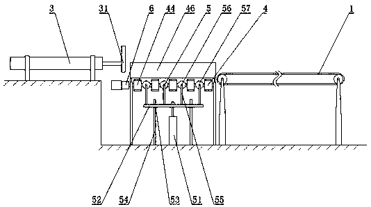
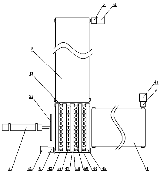
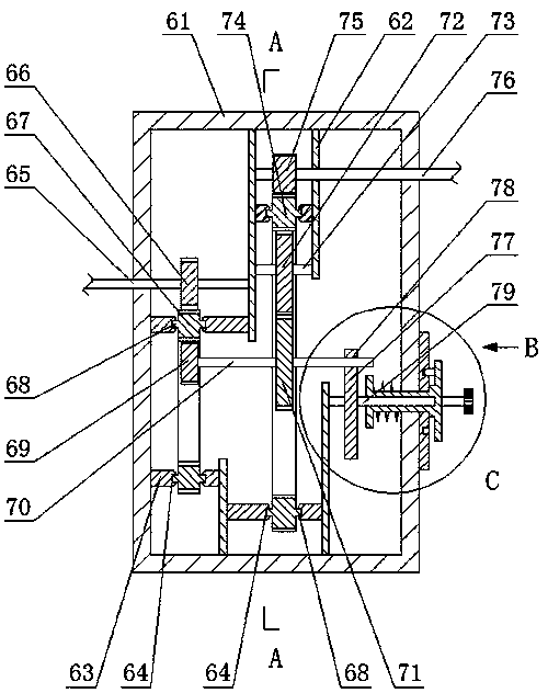
[0030] The embodiment of the present invention provides a right-angle turning conveying device and its working method. By setting the steering gear 4, the pulley unit 5 and the pushing cylinder 3, the transported items can be moved by the pulley unit when moving from the belt conveyor B2 to the steering gear 4. 5 is jacked up, and then pushed by the pushing cylinder 3 to the belt conveyor A1, so as to realize the automatic turning of the goods to be transported, and solve the technical problem of inconvenience in loading and unloading caused by the combined use of multiple conveying devices. By setting the transmission 6, it is convenient for the production line operators to adjust the speed of the conveying device, thereby solving the technical problem that the current conveying device is not convenient for speed adjustment. By adjusting the adjusting wheel 77 in the transmission 6, the gear C71 can be meshed with different gears in the speed adjusting wheel set 72 to obtain di...


PUM


Abstract

The invention discloses a right-angle turning conveying device and its working method, comprising a belt conveyor A and a belt conveyor B, characterized in that: the belt conveyor A and the belt conveyor B are arranged at an angle of 90°, the belt conveyor A and the belt conveyor The intersection of the machine B is provided with a steering gear, the bottom of the steering gear is provided with a pulley unit, one side of the steering gear is provided with a push cylinder, and the belt conveyor A, belt conveyor B, and the steering gear are all provided with motors, The steering gear also includes a frame on which a rotating shaft A and a rotating shaft B are rotatably connected, one end of the rotating shaft A is fixedly connected to the output end of the motor, and the rotating shaft A and the rotating shaft B are evenly spaced A plurality of belt pulleys are sleeved, and a belt is connected between the belt pulley sleeved on the rotating shaft A and the belt pulley sleeved on the rotating shaft B. The purpose of the present invention is to solve the problems of inconvenient loading and unloading, inability of the conveying devices to turn, and inconvenient speed adjustment of the conveying devices caused by the combined use of multiple conveying devices.

Description

Technical field [0001] The invention belongs to the field of workshop conveyor systems, and in particular relates to a right-angle turning conveying device and a working method thereof. Background technique [0002] Automated conveying device refers to the work of transporting and conveying by the automated conveyor system instead of manual, transporting the conveying object from one station to another. The manual task is only to adjust, supervise and manage the automatic line, without directly participating in the handling work , The automatic conveying device has a strict rhythm, can replace a large amount of manual work, greatly reduces the workload of personnel, and is of great significance to production. It has become an inaccessible part of automated production. [0003] Existing automated conveying devices are generally linear conveyor lines, and the transported items can only run along a straight line. If the transported items need to be transferred to other conveyor lines,...

Claims


Application Information

Patent Timeline
Patent Type & Authority Patents(China)
IPC IPC(8): B65G47/57B65G47/24B65G43/08B65G47/82B65G23/30
CPCB65G23/30B65G43/08B65G47/24B65G47/57B65G47/82B65G2203/042
Inventor 卢永刚吕振禾
Owner 山东炎黄工业设计有限公司
Learn More