CCD die cutting machine

A die-cutting machine and die-cutting technology, which is applied in the field of CCD die-cutting machines, can solve the problems of incapable of processing complex typesetting materials, material position tolerances, and difficult processing, so as to avoid tolerance accumulation, precise processing positions, and reduce waste. Effect

Pending Publication Date: 2020-03-27
宏文科技(广东)有限公司
View PDF0 Cites 6 Cited by
  • Summary
  • Abstract
  • Description
  • Claims
  • Application Information

AI Technical Summary

Problems solved by technology

[0002] Existing die-cutting machines generally use manual loading and unloading or automatic loading and unloading mechanisms to fix the material in a jig, and then start the equipment for punching. This punching method requires mature technology and relatively low cost. However, in this kind of processing method, the processing materials are generally fed at intervals, and they can only be punched in one direction during punching, which will generate more waste and cannot process materials with complex layouts, and gap feeding will cause the material to be out of position. Tolerance, when the number of processing is more, the tolerance will be larger, it needs to be adjusted manually, and for high-precision materials such as keyboard film circuit boards and printed matter, more accurate fixtures are needed for fixing, and the loading and unloading mechanism needs to be adjusted many times parameters, because the thinner the material, the higher the accuracy requirements for the boundary and the greater the processing difficulty

Method used


Image

  • CCD die cutting machine
  • CCD die cutting machine
  • CCD die cutting machine

Examples


Embodiment Construction

[0020] In order to make the above objects, features and advantages of the present invention more comprehensible, specific implementations of the present invention will be described in detail below in conjunction with the accompanying drawings. It should be noted that all the drawings of the present invention are in simplified form and use imprecise ratios, which are only used to facilitate and clearly assist the purpose of illustrating the embodiments of the present invention.

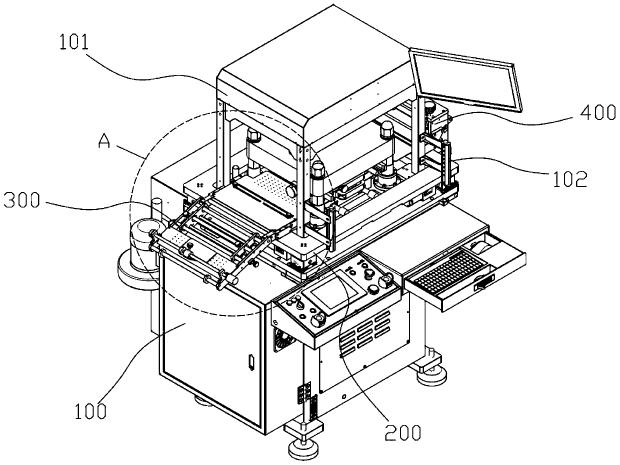
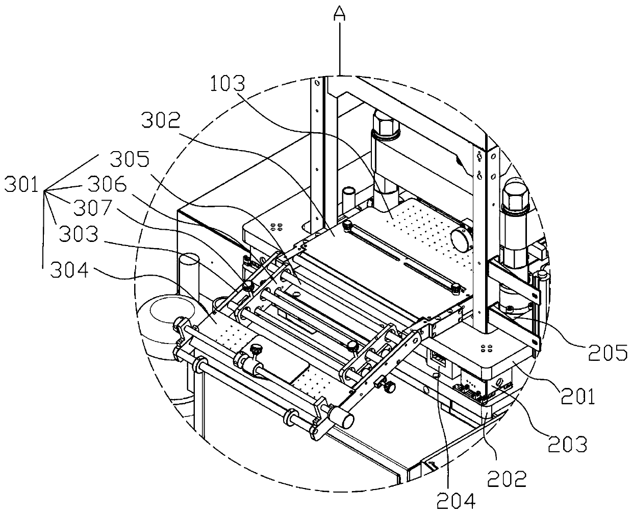
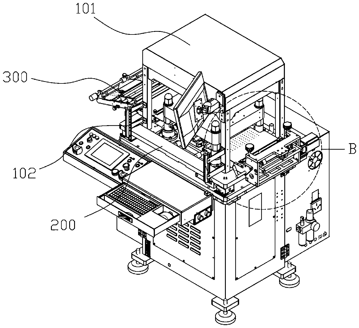
[0021] Such as Figure 1 to Figure 6 As shown, the present invention discloses a CCD die-cutting machine, a CCD die-cutting machine, including a workbench 100, a frame 101 arranged on the workbench 100, a computer; an alignment platform 200, a feeding mechanism 300, a blanking mechanism 400, a die-cutting mechanism 500, and a CCD vision component 600; the right side of the frame 101 corresponding to the die-cutting mechanism 500 is also provided with an infrared hand guard 102;

[0022] The alignment ...


PUM


Abstract

The invention discloses a CCD die cutting machine comprising a workbench, a frame and a computer. The CCD die cutting machine further comprises an alignment platform, a material supplying mechanism, afeeding mechanism, a die cutting mechanism and a CCD visual assembly. The material supplying mechanism and the feeding mechanism are arranged on the alignment platform and used for traction of a machined material. The die cutting mechanism is arranged between the material supplying mechanism and the feeding mechanism and used for machining the machined material which reaches the die cutting mechanism through traction by the material supplying mechanism and the feeding mechanism. The CCD visual assembly comprises a CCD visual camera electrically connected with the computer. The visual direction of the CCD visual camera is directed at the die cutting mechanism, and the CCD visual camera collects images of the machined material and sends the information to the computer for analysis. When themarked center point of the machined material coincides with a center point set by the computer, the computer sends an instruction to the die cutting mechanism to conduct die cutting. Compared with anexisting die cutting machine, the CCD die cutting machine has the advantages of automatic die cutting, accurate machining position and less production waste.

Description

technical field [0001] The invention relates to the technical field of die-cutting machines, in particular to a CCD die-cutting machine. Background technique [0002] Existing die-cutting machines generally use manual loading and unloading or automatic loading and unloading mechanisms to fix the material in a jig, and then start the equipment for punching. This punching method requires mature technology and relatively low cost. However, in this kind of processing method, the processing materials are generally fed at intervals, and they can only be punched in one direction during punching, which will generate more waste and cannot process materials with complex layouts, and gap feeding will cause the material to be out of position. Tolerance, when the number of processing is more, the tolerance will be larger, it needs to be adjusted manually, and for high-precision materials such as keyboard film circuit boards and printed matter, more accurate fixtures are needed for fixing...

Claims


Application Information

Patent Timeline
IPC IPC(8): B26F1/38B26D5/08B26D5/00B26D7/02B26D7/06B26D7/01B26D7/32
CPCB26F1/38B26D5/086B26D5/007B26D7/018B26D7/06B26D7/01B26D7/32
Inventor 徐万志贺洪文
Owner 宏文科技(广东)有限公司
Why Eureka
Try Eureka