Clamping and positioning device for cutting metallographic sample and clamping and positioning method thereof

A technology for clamping and positioning metallographic samples, which is applied in the direction of positioning devices, sampling devices, and preparation of test samples. Effective clamping and fixing to improve cutting efficiency

Pending Publication Date: 2020-03-27
东莞市特种设备检测与节能技术服务中心有限公司
View PDF0 Cites 5 Cited by
  • Summary
  • Abstract
  • Description
  • Claims
  • Application Information

AI Technical Summary

Problems solved by technology

The fixture can only move in one direction along the T-shaped slot on the workbench, and cannot flexibly adjust its position in the horizontal and vertical ranges. Therefore, the adjustment of the relative position between the sample and the cutting knife is limited, and it is impossible to precisely position and cut the sample. Cut from the desired sample part, when the sample area is too small, the equipment may not be able to cut the sample
At present, the clamping device provided by the metallographic cutting machine is mainly suitable for the clamping of regular-shaped samples, while the clamping of irregular-shaped samples is more complicated and inefficient, and often the clamping is not tight or even impossible to clamp, making Special-shaped samples cannot be clamped and cut
If the sample is not clamped tightly, it is easy to slide and fall off during cutting, so that the sample cannot be cut accurately, and the cutting equipment may be damaged

Method used


Image

  • Clamping and positioning device for cutting metallographic sample and clamping and positioning method thereof
  • Clamping and positioning device for cutting metallographic sample and clamping and positioning method thereof
  • Clamping and positioning device for cutting metallographic sample and clamping and positioning method thereof

Examples


Embodiment Construction

[0030] In order to facilitate the understanding of those skilled in the art, the present invention will be further described below in conjunction with the embodiments and accompanying drawings, and the contents mentioned in the embodiments are not intended to limit the present invention.

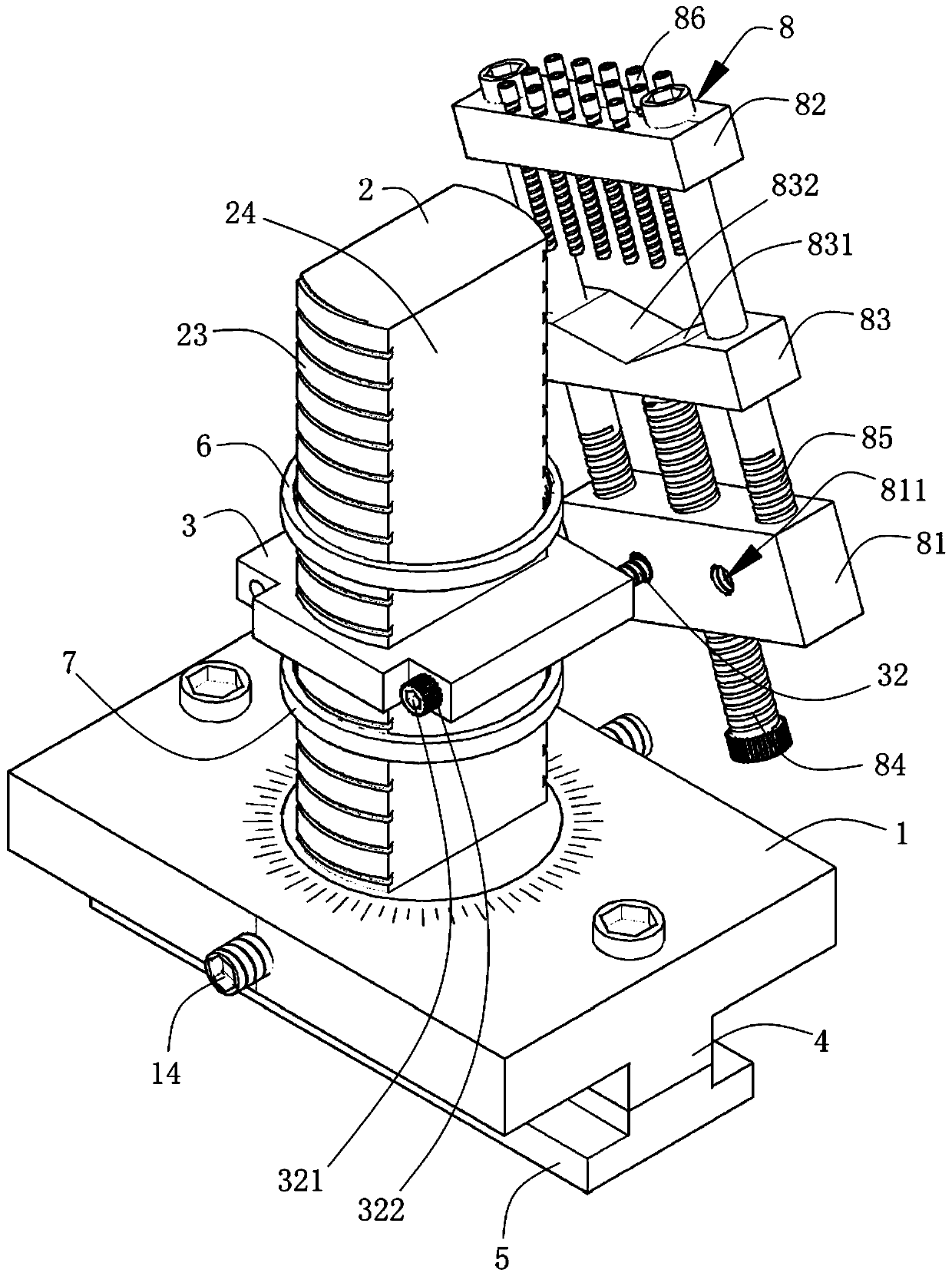
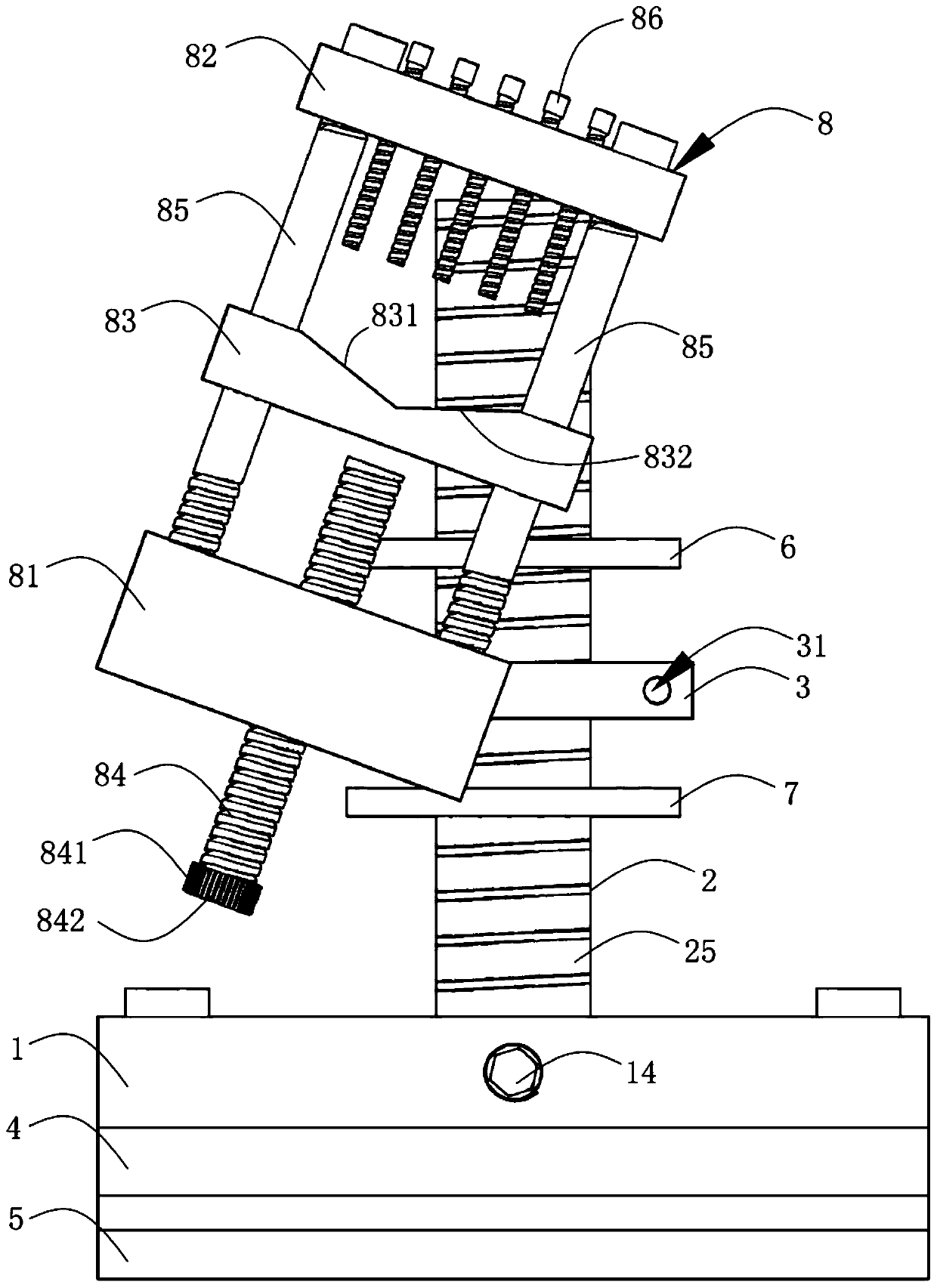
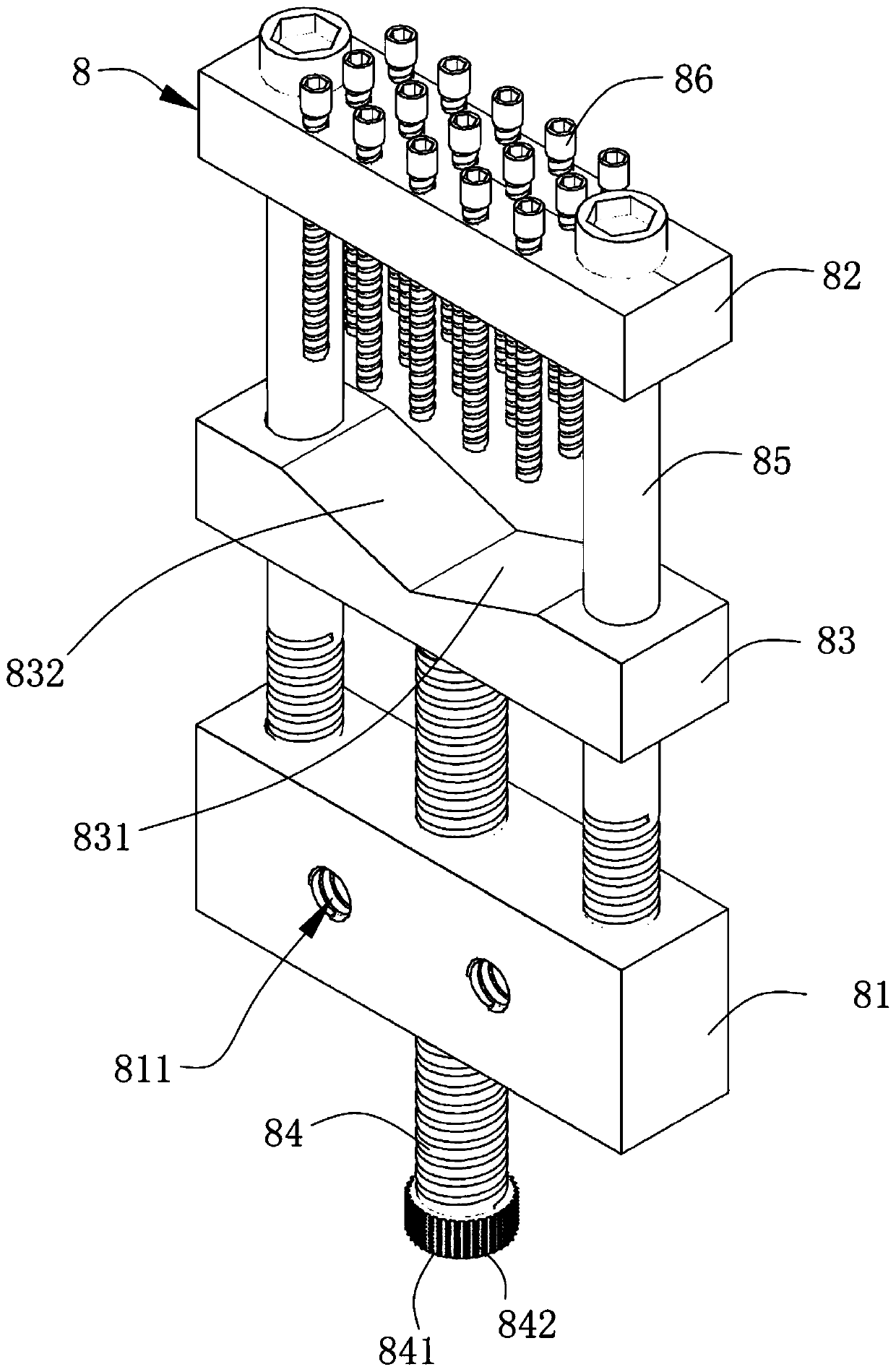
[0031] Such as Figure 1 to Figure 7 As shown, the present invention provides a clamping and positioning device for cutting metallographic samples, which includes a bracket mechanism and a clamp mechanism 8 that is movably installed on the bracket mechanism. The bracket 2 of the base 1, the sliding sleeve 3 moving along the length direction of the bracket 2, the sliding sleeve adjusting and locking assembly for positioning the sliding sleeve 3 on the bracket 2, the slider 4 designed integrally with the bracket base 1 and installed on The locking base 5 of the slider 4; the clamp mechanism 8 includes a supporting block 81, an upper clamping block 82, a lower clamping block 83, a top tightenin...


PUM


Abstract

The invention relates to the technical field of metallographic cutting, in particular to a clamping and positioning device for cutting a metallographic sample and a clamping and positioning method thereof. The clamping and positioning device comprises a support mechanism and a clamp mechanism, wherein the support mechanism comprises a support base, a support, a sliding sleeve, a sliding sleeve adjusting and locking assembly, a sliding block and a locking base, and the clamp mechanism comprises a supporting block, an upper clamping block, a lower clamping block, a jacking screw, two supportingguide rods and a plurality of pressing screws. When a metallographic cutting machine is used for cutting the special-shaped sample, the clamping and positioning device can effectively clamp and fix the special-shaped sample, the sample is firmly locked, thus loosening or falling in the cutting process is avoided, the sample cutting is precise without damaging equipment, the relative positions of the sample and the cutting knife can be conveniently and flexibly adjusted, and precise positioning is realized, so that the required sample part can be cut, the cutting requirement is met without frequently replacing a clamp, the labor intensity is reduced, the cutting efficiency is improved, and the equipment is effectively maintained.

Description

technical field [0001] The invention relates to the technical field of metallographic cutting, in particular to a clamping and positioning device for cutting metallographic samples and a clamping and positioning method thereof. Background technique [0002] In the metallographic analysis of metal materials, the sample needs to go through a series of pretreatment steps such as cutting, inlaying, grinding, polishing, and etching. Selecting a suitable cutting site and cutting out a sample of a suitable size is a very important part of the pretreatment. At present, most metallographic cutting machines are equipped with a T-slot table as standard. When cutting the sample, the sample needs to be clamped on the clamping device and then locked and fixed on the T-slot table of the cutting machine. The fixture can only move in one direction along the T-shaped slot on the workbench, and cannot flexibly adjust its position in the horizontal and vertical ranges. Therefore, the adjustmen...

Claims


Application Information

Patent Timeline
Patent Type & Authority Applications(China)
IPC IPC(8): B23Q3/06G01N1/04G01N1/28
CPCB23Q3/062G01N1/04G01N1/286G01N2001/2873
Inventor 肖冬飞王瑄侯冀川刘芝花韦中悬徐诚欧建华
Owner 东莞市特种设备检测与节能技术服务中心有限公司
Why Eureka
Try Eureka