
Automatic wire clamping guide device for magnetic ring winding machine

A technology of guiding device and winding wire, which is applied in coil manufacturing, inductance/transformer/magnet manufacturing, electrical components, etc., can solve the problems of increasing design space and structure complexity, and achieve simple structure, lower positioning accuracy, and wire clamping Accurate and fast results

Pending Publication Date: 2020-03-24
ZHONGSHAN COMPETENT AUTOMATION EQUIP CO LTD
View PDF0 Cites 2 Cited by
  • Summary
  • Abstract
  • Description
  • Claims
  • Application Information

AI Technical Summary

Problems solved by technology

[0002] At present, there are more and more types of magnetic winding machines due to the different magnetic rings. For crochet needle winding machines, for the crochet needles that stretch up and down in the magnetic ring, multiple limit block guides are required when the wire is fed. The winding direction ensures that the thread can be hooked by the crochet needle after passing through the center of the magnetic ring, which greatly increases the complexity of the design space and structure

Method used


Image

  • Automatic wire clamping guide device for magnetic ring winding machine
  • Automatic wire clamping guide device for magnetic ring winding machine
  • Automatic wire clamping guide device for magnetic ring winding machine

Examples


Embodiment Construction

[0023] The present invention will be further described in detail below in conjunction with the accompanying drawings of the specification:

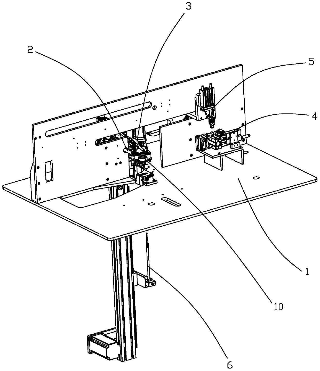
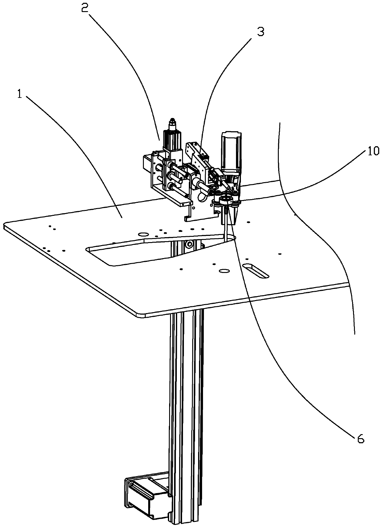
[0024] Such as Figure 1-6 As shown, an automatic thread-clamping guide device for a magnetic winding machine includes a thread-clamping mechanism 2 arranged on a frame 1 that can be retracted close to or away from the winding conveying direction. The frame 1 is also provided with a thread-clamping mechanism 2 On the wire-in side, a wire transfer mechanism 3 that can expand and contract to deviate the winding wire from its transmission line.

[0025] Specifically, the winding transmission direction passes through the torus of the magnetic ring 10, the wire clamping mechanism 2 clamps the winding from the wire exiting end of the winding through the torus of the magnetic ring 10, and the wire transfer mechanism 3 moves from the toroid of the magnetic ring 10 to make The winding deviates from its conveying route to facilitate winding and hooking....


PUM


Abstract

The invention discloses an automatic wire clamping guide device for a magnetic ring winding machine. The device comprises a wire clamping mechanism which is arranged on a rack and can be telescopically close to or far away from the winding conveying direction, and a wire moving mechanism which is positioned on the wire inlet side of the wire clamping mechanism and can be telescopically deviated from the conveying line of the wire clamping mechanism is also arranged on the rack. According to the invention, the wire clamping mechanism is matched with the wire moving mechanism and can be matchedwith the wire winding crochet hook to accurately and quickly hook wires, so that the positioning precision of the wire winding direction is reduced and the use is more flexible and stable. According to the telescopic wire clamping assembly of the wire clamping mechanism, the wire clamping shaft sleeve and the wire clamping shaft rotate relatively to open and close wire clamping, the structure is simple, and wire clamping is accurate and rapid.

Description

【Technical Field】 [0001] The invention relates to an automatic thread clamping guide device for a magnetic winding machine, belonging to the technical field of automatic winding production of magnetic rings. 【Background technique】 [0002] At present, the types of magnetic winding machines are becoming more and more diverse due to the different magnetic rings. Crochet type winding machines are aimed at the crochet needles that stretch up and down in the magnetic ring. The winding requires multiple limit blocks to guide when feeding the wire. The winding direction ensures that the wire can be hooked by the hook needle after passing through the center of the magnetic ring, which greatly increases the complexity of the design space and structure. [Content of the invention] [0003] The purpose of the present invention is to overcome the shortcomings of the prior art and provide an automatic wire clamping device for a magnetic winding machine that reduces the positioning accuracy of t...

Claims


Application Information

Patent Timeline
Patent Type & Authority Applications(China)
IPC IPC(8): H01F41/08H01F41/096
CPCH01F41/08H01F41/096
Inventor 周珂陈慧廖述艳马细艳黄奇翰熊刚廖述林
Owner ZHONGSHAN COMPETENT AUTOMATION EQUIP CO LTD
Learn More