
Novel energy-saving transformer

An energy-saving transformer and a new type of technology, applied in the direction of transformer/inductor magnetic core, transformer/inductor parts, electrical components, etc. The problem of poor support effect, etc., can avoid the phenomenon of unbalanced force, ensure safe and stable operation, and improve the ability of mechanical force.

Pending Publication Date: 2020-03-24
LIRUITE ELECTRIC CO LTD
View PDF0 Cites 1 Cited by
  • Summary
  • Abstract
  • Description
  • Claims
  • Application Information

AI Technical Summary

Problems solved by technology

[0002] The iron yoke structure of the traditional transformer iron core is cylindrical. After the core column is assembled, in order to ensure the mechanical strength of the winding end and the ability of the transformer to withstand short-circuit electromotive force, the winding end support plate must be welded on the upper and lower clamps of the iron yoke, so that The clamping structure of the iron core is too complicated, and the end support effect is not good at the same time, the fastening force of the upper and lower ends of the transformer is insufficient. The long-term safe and stable operation of the transformer has a certain impact; moreover, the existing transformers generally have the problems of poor energy saving effect, low heat dissipation performance, and time-consuming and laborious installation, which brings certain limitations in the actual use process. Therefore, how to provide a new type of energy-saving transformer with good energy-saving effect and time-saving and labor-saving installation has become an important issue to be solved at present.

Method used


Image

  • Novel energy-saving transformer
  • Novel energy-saving transformer
  • Novel energy-saving transformer

Examples


Embodiment Construction

[0019] In order to make the purpose, technical solutions and advantages of the embodiments of the present invention clearer, the technical solutions in the embodiments of the present invention will be clearly and completely described below in conjunction with the accompanying drawings in the present invention. Obviously, the described embodiments are the Some embodiments of the invention are not all embodiments. Based on the embodiments of the present invention, all other embodiments obtained by those of ordinary skill in the art without creative efforts fall within the protection scope of the present invention.

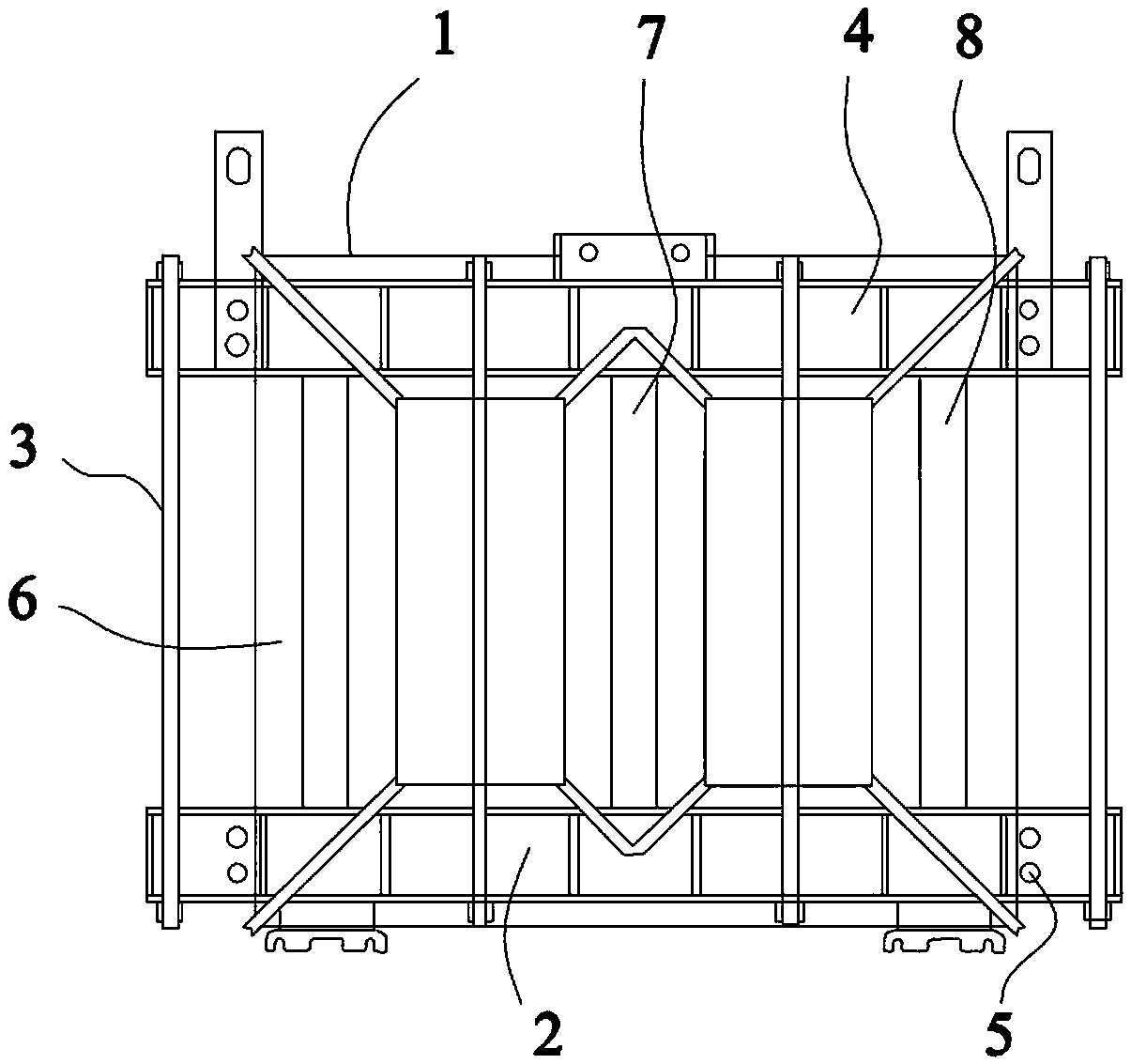
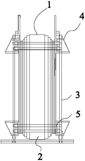
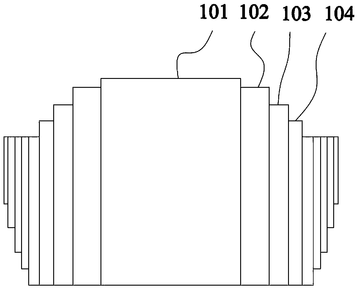
[0020] Such as figure 1 and figure 2 As shown, a new type of energy-saving transformer, including windings and iron core, the iron core is a six-stage 45° fully oblique joint stacked structure, such as Figure 4 and Figure 5 As shown, the oblique joints appear alternately in the iron core lamination, so the magnetic flux distribution is uniform. Magnetic density...


PUM


Abstract

The invention provides a novel energy-saving transformer. An upper clamp assembly and the lower clamp assembly form a frame structure after passing through a transverse opposite-pull screw and a vertical opposite-pull screw. The upper clamp assembly and the lower clamp assembly are the same in structure. Each clamp assembly is composed of two clamping pieces which are arranged in the length direction of the transformer and symmetrically arranged on the two sides of an upper iron yoke; the whole clamping piece is of a U-shaped groove structure. The outer sides of the bottoms of the U-shaped groove-shaped structures cling to the side surfaces of the upper and lower iron yokes; the lengths of the two vertical edges of the U-shaped groove-shaped structure are different; the supporting area ofthe end of a transformer winding is effectively increased, the stress condition of the end of the winding is improved, the unbalanced stress phenomenon of the winding is avoided, the self-gravity borne by the transformer and the capacity of mechanical force generated when the transformer is short-circuited are effectively improved, the damage rate of the transformer in a fault state is effectivelyreduced, and safe operation of a power grid is guaranteed. Meanwhile, the clamping piece structure of the transformer iron core is simplified, and great convenience is brought to work such as installation of the transformer.

Description

technical field [0001] The invention belongs to the technical field of electric equipment manufacturing, and in particular relates to a novel energy-saving transformer. Background technique [0002] The iron yoke structure of the traditional transformer iron core is cylindrical. After the core column is assembled, in order to ensure the mechanical strength of the winding end and the ability of the transformer to withstand short-circuit electromotive force, the winding end support plate must be welded on the upper and lower clamps of the iron yoke, so that The clamping structure of the iron core is too complicated, and the end support effect is not good at the same time, the fastening force of the upper and lower ends of the transformer is insufficient. The long-term safe and stable operation of the transformer has a certain impact; moreover, the existing transformers generally have the problems of poor energy saving effect, low heat dissipation performance, and time-consumin...

Claims


Application Information

Patent Timeline
Patent Type & Authority Applications(China)
IPC IPC(8): H01F27/245H01F27/26
CPCH01F27/245H01F27/263
Inventor 张华旭王安冯铎白冰洋李文喆随向前周罗鹏冯建海
Owner LIRUITE ELECTRIC CO LTD
Learn More