
Air duct connecting and inserting device and using method thereof

A technology of a plug-in device and a connecting device, which is applied in the directions of pipes/pipe joints/pipes, passing components, mechanical equipment, etc., can solve the problems of poor sealing performance of angle iron flanges, increase labor costs, increase the weight of ships, etc., and achieve sealing effect. Good, save labor cost, save construction time effect

Inactive Publication Date: 2020-03-24
COSCO SHIPPING SHIPYARD (NANGTONG) CO LTD +1
View PDF9 Cites 0 Cited by
  • Summary
  • Abstract
  • Description
  • Claims
  • Application Information

AI Technical Summary

Problems solved by technology

[0002] At present, in ship construction, the installation of the air duct is the traditional angle iron flange connection method. Due to the limited space of the ship, the air duct is on the top of the cabin, and there is often space interference with electrical and piping systems. The existing The space occupied by the angle iron flange is 60mm-150mm. This kind of flange is connected by bolts, which increases the weight of the ship. In general offshore engineering projects, if the ship is overweight, the ship owner and the shipyard will clearly stipulate when signing the contract. Weight, if one ton is overweight, the fine is often more than 50,000 US dollars; the bolted connection not only increases the weight of the hull, but also takes a long time to install the connection, which increases labor costs, and the sealing performance of traditional angle iron flanges is poor

Method used


Image

  • Air duct connecting and inserting device and using method thereof
  • Air duct connecting and inserting device and using method thereof
  • Air duct connecting and inserting device and using method thereof

Examples


Embodiment Construction

[0036] In order to deepen the understanding of the present invention, the present invention will be further described below in conjunction with the embodiments and accompanying drawings. The embodiments are only used to explain the present invention and do not constitute a limitation to the protection scope of the present invention.

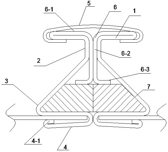
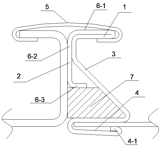
[0037] Such as Figure 1-8 It shows an embodiment of an air duct connecting device of the present invention: it includes a locking cover 5 and an air duct connecting device, and an air duct connecting device is installed at one end of the locking cover 5, or on the locking cover 5 The two ends of 5 are mirror-imaged with an air duct connecting device, the air duct connecting device includes a transverse locking part 1, a longitudinal connecting part 2, a sealing part 3 and a clamping part 4, and the longitudinal connecting part 2 is set at the transverse locking One end of the part 1 is perpendicular to the end face of the transverse locking part...


PUM


Abstract

The invention relates to an air duct connecting and inserting device and a using method thereof. The device comprises a locking cover and an air duct connecting device, the air duct connecting deviceis installed at one end of the locking cover, or air pipe connecting devices are installed at the two ends of the locking cover in a mirror image mode. The air duct connecting device comprises a transverse locking part, a longitudinal connecting part, a sealing part and a clamping part, wherein the longitudinal connecting part is arranged at one end of the transverse locking part, is perpendicularto the end face of the transverse locking part and extends downwards, a sealing mounting part is arranged at the lower end of the longitudinal connecting part, the clamping part is arranged at the lower end of the sealing mounting part, the transverse locking part is clamped in the locking cover, and a sealing strip is arranged in the sealing mounting part. The device has the advantages that theconnecting height is reduced, and the space at the top of a cabin is greatly saved; the weight of a traditional connecting flange is reduced, the construction time is shortened, and the labor cost isreduced; compared with traditional angle iron flange construction, the construction time and the labor cost are saved by more than 60%; the connection is tight, the strength is large, and the sealingeffect is good.

Description

technical field [0001] The invention relates to a connecting device for an air pipe without an angle iron flange for ocean engineering equipment and ships, in particular to an air pipe connecting device. Background technique [0002] At present, in ship construction, the installation of the air duct is the traditional angle iron flange connection method. Due to the limited space of the ship, the air duct is on the top of the cabin, and there is often space interference with electrical and piping systems. The existing The space occupied by the angle iron flange is 60mm-150mm. This kind of flange is connected by bolts, which increases the weight of the ship. In general offshore engineering projects, if the ship is overweight, the ship owner and the shipyard will clearly stipulate when signing the contract. The weight, one ton overweight, is often fined more than 50,000 US dollars; the bolted connection not only increases the weight of the hull, but also takes a long time to in...

Claims


Application Information

Patent Timeline
Patent Type & Authority Applications(China)
IPC IPC(8): F16L25/00
CPCF16L25/0009
Inventor 李荣张晓栋万家平杨勇仇明
Owner COSCO SHIPPING SHIPYARD (NANGTONG) CO LTD
Learn More