Concrete mixing device for bridge construction

A stirring device and a technology for construction, applied in the field of bridge construction, can solve problems such as uneven stirring, self-solidification and deposition, and achieve the effects of ensuring mixing quality, avoiding self-solidification and deposition, and improving quality and efficiency.

Active Publication Date: 2020-12-15
建湖上冈产业园服务有限公司
View PDF7 Cites 0 Cited by
  • Summary
  • Abstract
  • Description
  • Claims
  • Application Information

AI Technical Summary

Problems solved by technology

The existing concrete mixing device for bridge construction has the disadvantage of uneven mixing, and it is prone to self-solidification and deposition when it is transported outside after mixing

Method used


Image

  • Concrete mixing device for bridge construction
  • Concrete mixing device for bridge construction
  • Concrete mixing device for bridge construction

Examples


Embodiment 1

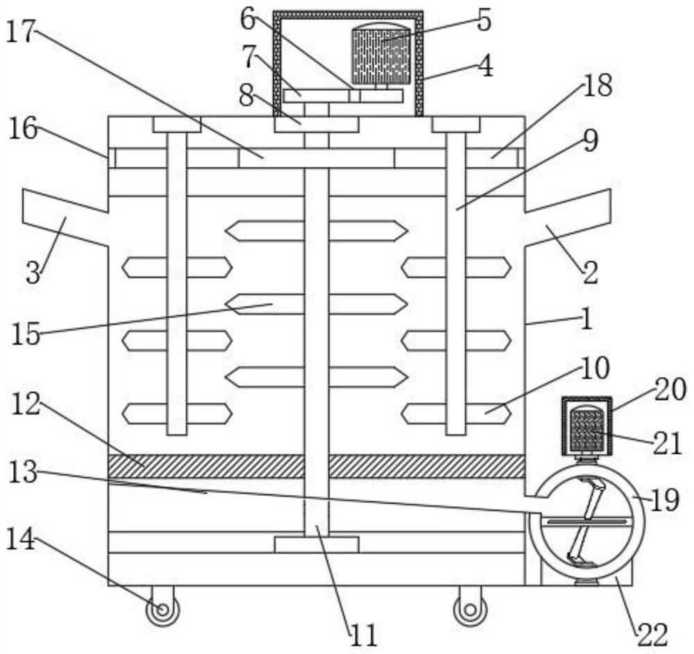
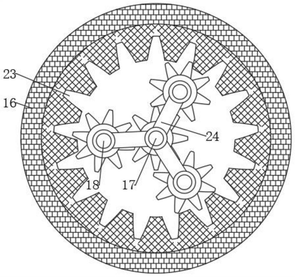
[0020] see Figure 1-3 , a concrete mixing device for bridge construction, comprising a cavity 1, a first material inlet 2 and a second material inlet 3 are respectively arranged on the left and right sides of the cavity 1, and a stirring shaft 11 is arranged in the cavity 1. A plurality of stirring blades 15 are equidistantly arranged on the shaft 11, and the stirring shaft 11 is fixed inside the cavity 1 by a fixed bearing 8, and one end of the stirring shaft 11 extends to the outside of the cavity 1 and is connected with a driving mechanism; the stirring shaft A plurality of driven shafts 9 are evenly arranged on the periphery of 11, the number of driven shafts 9 is not less than three, the driven shaft 9 is connected to the stirring shaft 11, and a plurality of driven blades are equidistantly arranged on the driven shaft 9 10. A detachable baffle 12 is arranged inside the cavity 1 , and an inclined discharge platform 13 is arranged below the baffle 12 , and the discharge p...

Embodiment 2

[0030] In Embodiment 1, the cavity 1 is placed on the ground during actual use, and it takes a lot of manpower to move or place the equipment; therefore, this embodiment is improved on the basis of Embodiment 1. It is: a roller 14 is arranged below the cavity 1, so as to facilitate the movement and placement of the stirring device.


PUM


Abstract

The invention discloses a concrete stirring device used for bridge constructions. The concrete stirring device comprises a cavity. A first feed port and a second feed port are formed in the two sidesof the cavity correspondingly. A stirring shaft is arranged in the cavity. Multiple stirring blades are arranged on the stirring shaft at equal intervals. One end of the stirring shaft is connected with a drive mechanism. According to the concrete stirring device used for the bridge constructions, by arranging multiple driven shafts, linked with the stirring shaft, on the periphery of the stirringshaft, concrete can be stirred in the cavity in an omnidirectional manner; by arranging a conveying pipe on one side of the cavity, the concrete can be conveniently conveyed out rapidly; and a swinging blade is arranged in the conveying pipe, the situation that self-solidification and deposition are caused when the concrete is conveyed in the conveying pipe can be effectively avoided, and the quality of the concrete conveyed out through the conveying pipe is ensured. In addition, by arranging an observation window on one side of the cavity, operators can conveniently check the concrete stirring situation all the time, and the work quality and efficiency are improved.

Description

technical field [0001] The invention relates to the technical field of bridge construction, in particular to a concrete mixing device for bridge construction. Background technique [0002] Architecture is the general term for buildings and structures. It is an artificial environment created by people using the material and technological means they have mastered and certain scientific laws and aesthetic laws to meet the needs of social life. Concrete refers to the collective name of engineering composite materials that use cementitious materials to cement aggregates into a whole. The term concrete usually refers to the use of cement as cementitious material, sand and stone as aggregate, and water in a certain proportion. , The cement concrete obtained by mixing, also known as ordinary concrete, is widely used in civil engineering. The existing concrete mixing device for bridge construction has the disadvantage of uneven mixing, and the phenomenon of self-solidification and d...

Claims


Application Information

Patent Timeline
Patent Type & Authority Patents(China)
IPC IPC(8): B28C5/16B28C7/06B28C7/12B28C7/16
CPCB28C5/16B28C7/06B28C7/12B28C7/16
Inventor 王敏帆
Owner 建湖上冈产业园服务有限公司
Why Eureka
Try Eureka