


Quick Research
Generate reliable direction feasibility study reports for your R&D in just a few steps.

Technical Q&A
Discover and master advanced knowledge NOW. Basics, ideas, possibilities, all at once.

Find Solutions
As an expert in R&D theories, this can generate solutions to your technical problems instantly.

Evaluate Feasibility
Analyze your overall solution with one click, know your potential R&D risks in advance.

Monitor Landscape
Get weekly tech updates, stay abreast of the latest tech innovations and key insights.
A kind of solid wood bending equipment and technology thereof
A bending and equipment technology, applied in the field of solid wood bending equipment and its process, can solve the problems of reduced strength of curved parts, rough curved surface, difficult to paint and finish, etc., and achieve the effect of long service life, small internal stress and enhanced strength
- Summary
- Abstract
- Description
- Claims
- Application Information
AI Technical Summary
Problems solved by technology
Method used
Image

Examples
Embodiment 1
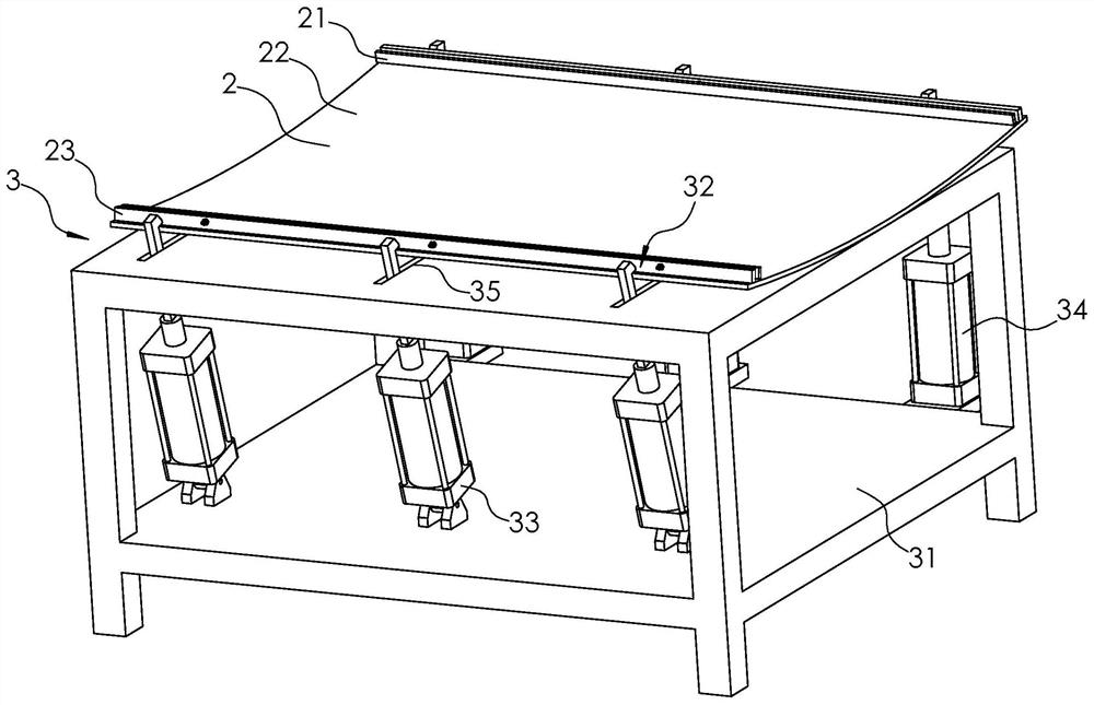
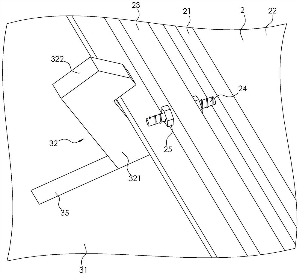
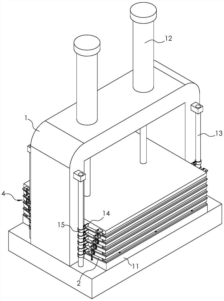
[0042] Embodiment one: if figure 1 and image 3 As shown, a solid wood bending equipment includes a frame 1, a metal plate 2, a pressing device 3, a conveyor belt, a linkage assembly 4, a number of heating plates 11 arranged sequentially from top to bottom, and a driving member located above the heating plate 11; The upper surface of the metal plate 2 is provided with two groups of clamping plates 21, and the pressing device 3 can press the metal plate 2 to be flat. At this time, the two groups of clamping plates 21 and the metal plate 2 jointly form a placement cavity 22, and the workers can Arrange the wood in the placement cavity 22; when the pressing of the metal plate 2 by the pressing device 3 is canceled, the two groups of clamping plates 21 will be clamped on the wood together; then the conveyor belt (not shown) will put the The metal plate 2 is transported to the heating plate 11, and the linkage assembly 4 can drive all the metal plates 2 to rise and fall synchronou...
Embodiment 2
[0055] Embodiment two: a kind of craft of solid wood bending equipment, comprises the following steps:
[0056] S1. First place the metal plate 2 on the workbench 31, then turn the first hydraulic cylinder 33 to a proper position according to the specifications of the metal plate 2, and then drive the pressure plate 32 through the first hydraulic cylinder 33 and the second hydraulic cylinder 34 Descending, the two groups of pressing plates 32 will be pressed against the metal plate 2, so that the metal plate 2 is pressed to be flat;
[0057] S2. Arrange multiple groups of wood in the placement cavity 22 in order, and make the adjacent wood stick to each other, then clamp the wood through two sets of clamping plates 21, and then clamp the clamping plates 21 through the second nut 25 Locked and fixed on the mounting plate 23;
[0058] S3, cancel the compression of the metal plate 2 by two groups of pressing plates 32, and place the metal plate 2 with wood between the adjacent t...
PUM
 Abstract
Description
Claims
Application Information
 - R&D Engineer
- R&D Manager
- IP Professional
- Industry Leading Data Capabilities
- Powerful AI technology
- Patent DNA Extraction
Browse by: Latest US Patents, China's latest patents, Technical Efficacy Thesaurus, Application Domain, Technology Topic, Popular Technical Reports.
© 2024 PatSnap. All rights reserved.Legal|Privacy policy|Modern Slavery Act Transparency Statement|Sitemap|About US| Contact US: help@patsnap.com