An Infrared Monitoring and Control Method for Continuous Casting Fire Cutting and Post-cutting Conveying Device

An infrared monitoring and control method technology, applied in the direction of electrical program control, manufacturing tools, gas flame welding equipment, etc., can solve the problems of low precision of cutting length and cutting depth, prone to accidents, unstable data transmission, etc., to achieve Improve processing speed and control efficiency, reduce manual intervention operations, and ensure the effect of processing

Active Publication Date: 2021-07-23
XINXING DUCTILE IRON PIPES CO LTD
View PDF5 Cites 0 Cited by
  • Summary
  • Abstract
  • Description
  • Claims
  • Application Information

AI Technical Summary

Problems solved by technology

[0003] The continuous casting torch cutter is an important component of the continuous casting machine. It is mainly used to cut the billet pulled out from the continuous casting mold by the continuous casting stretching and leveling machine into billets with a specific length and a specific cross-sectional shape. During the processing The operation of the equipment is controlled by the PLC controller, but the normal production and processing line is long, and the data transmission between the remote monitoring equipment and the PLC controller is unstable when the processing environment is poor, which affects the processing. The existing continuous casting fire cutting mechanism has low accuracy of cutting length and cutting depth of the slab, and often requires manual adjustment by workers, which affects processing efficiency and is prone to accidents. The infrared monitoring control method of the device is very necessary

Method used


Image

  • An Infrared Monitoring and Control Method for Continuous Casting Fire Cutting and Post-cutting Conveying Device
  • An Infrared Monitoring and Control Method for Continuous Casting Fire Cutting and Post-cutting Conveying Device
  • An Infrared Monitoring and Control Method for Continuous Casting Fire Cutting and Post-cutting Conveying Device

Examples


Embodiment 1

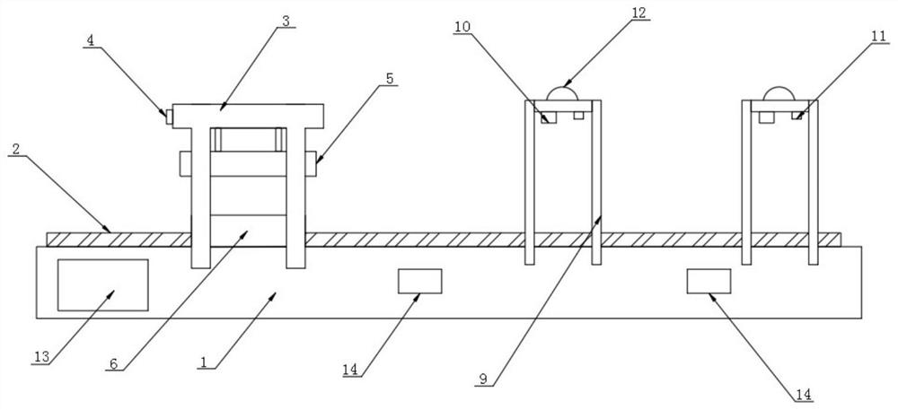
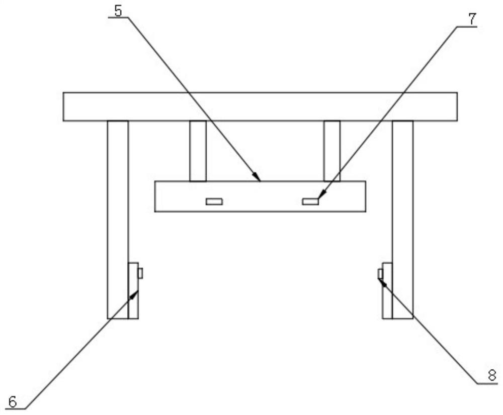
[0025] refer to Figure 1-3 The shown continuous casting fire-cutting and after-cut conveying device includes a cutting transmission device and a support frame, and the cutting transmission device includes a base 1, and a transmission panel 2 is provided on the top surface of the base 1, and the top surface of the transmission panel 2 is A support base 3 is provided, a laser range finder 4 is provided on the top and outside of the support base 3, a cutting mechanism 5 is connected to the bottom of the support base 3, and a clamping mechanism is provided on the front and rear surfaces of the transmission panel 2 6. The outer surface of the cutting mechanism 5 is evenly provided with a first infrared sensor 7, the inner surface of the clamping mechanism 6 is provided with a second infrared sensor 8, and the outer surface of the support seat 3 is evenly provided with a third infrared sensor 10, so The bottom surface of the third infrared sensor 10 is respectively provided with a ...

Embodiment 2

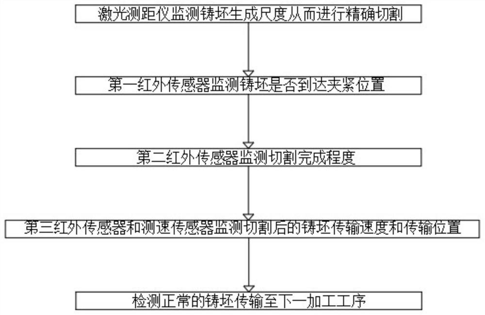
[0032] refer to Figure 1-3 An infrared monitoring and control method for a continuous casting torch cutting and post-cut conveying device includes the following steps:

[0033] Step 1: The slab to be cut is transmitted to the bottom of the support seat 3 on the transmission panel 2, and the laser rangefinder 4 measures and monitors the length of the slab passing through the support seat 3, and the first infrared sensor 7 pairs enter the cutting mechanism at the same time 5 Check whether the slab in the working area has reached the clamping position;

[0034] Step 2: When the predetermined length and position are reached, the clamping mechanism 6 clamps the billet from the front side and the rear side, and the cutting mechanism 5 cuts the clamped billet. During the cutting process, the second infrared sensor 8 monitors the cutting mechanism 5 Cutting completion degree, the cutting mechanism 5 and the clamping mechanism 6 stop working after reaching the predetermined specifica...


PUM


Abstract

The invention belongs to the field of continuous casting production, in particular to an infrared monitoring and control method for a continuous casting fire cutting and post-cutting conveying device, aiming at the problem of data transmission between the existing remote monitoring equipment and a PLC controller, the following is now proposed The solution includes a cutting transmission device, the cutting transmission device includes a base, a transmission panel is provided on the top surface of the base, a support seat is provided on the top of the transmission panel, and a laser range finder is provided on the outer side of the top of the support seat, so the The bottom of the support base is connected with a cutting mechanism, and the front and rear surfaces of the transmission panel are provided with clamping mechanisms. Multiple data transmission hosts are respectively responsible for data reception and transmission with the electrical components in the area, and the data is integrated and filtered, and then transmitted to the PLC controller. The PLC controller reads the data transmission host data signals and issues feedback commands. The data transmission host The feedback commands are sequentially transmitted to the corresponding electrical components to ensure the stable operation of the entire device system.

Description

technical field [0001] The invention relates to the technical field of continuous casting production, in particular to an infrared monitoring and control method of continuous casting fire cutting and post cutting conveying device. Background technique [0002] Continuous casting is an important part of steel production. Its main process is that high-temperature molten steel is strongly cooled inside the crystallizer to form a billet shell with a certain thickness, and the interior is still liquid steel. After entering the secondary cooling zone, the casting slab containing the liquid core coming out of the crystallizer continues to cool down under the strong cooling of the water nozzle or steam atomizing nozzle until the internal molten steel is completely solidified. [0003] The continuous casting torch cutter is an important component of the continuous casting machine. It is mainly used to cut the billet pulled out from the continuous casting mold by the continuous castin...

Claims


Application Information

Patent Timeline
Patent Type & Authority Patents(China)
IPC IPC(8): G05B19/02B23K7/00
CPCB23K7/00B23K7/10
Inventor 郝赫张位宁吴家礼贾建彬赵建郭森林侯水阶常超聂日光张世杰
Owner XINXING DUCTILE IRON PIPES CO LTD
Why Eureka
Try Eureka