Fly ash reinforced foam forming device for oil field and application thereof

A technology for fly ash and foam is applied in the fields of fly ash solid waste utilization technology and equipment and oil and gas field development engineering, which can solve the problems of fly ash agglomeration, particle deposition, and fly ash exposure to the air, and achieves a reduction in construction costs. Effect

Active Publication Date: 2020-03-24
CHINA UNIV OF PETROLEUM (BEIJING)
View PDF10 Cites 4 Cited by
  • Summary
  • Abstract
  • Description
  • Claims
  • Application Information

AI Technical Summary

Problems solved by technology

First of all, it is difficult for fly ash to be uniformly dispersed in the foaming agent solution, and fly ash is prone to agglomeration and precipitation, which is not conducive to the effective use of fly ash in the foam, which not only causes waste of raw materials, but also affects the stability of fly ash. bubble effect
At the same time, the particle size of the fly ash in the foam is not easy to control. In general, we can only rely on the particle size of the raw material of the fly ash, and the larger particle size or agglomerated fly ash is likely to cause particle deposition near the wellbore and block the near wellbore. reservoirs, it is difficult to achieve deep control and drive
In addition, the artificial feeding method will easily lead to the exposure of fly ash to the air, causing environmental pollution

Method used


Image

  • Fly ash reinforced foam forming device for oil field and application thereof
  • Fly ash reinforced foam forming device for oil field and application thereof
  • Fly ash reinforced foam forming device for oil field and application thereof

Examples


Embodiment Construction

[0070] The present invention will be further described below in conjunction with the accompanying drawings, but the present invention is not limited to the following embodiments.

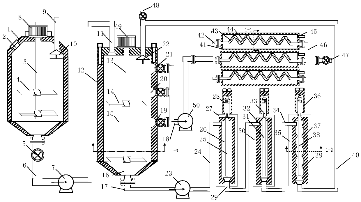
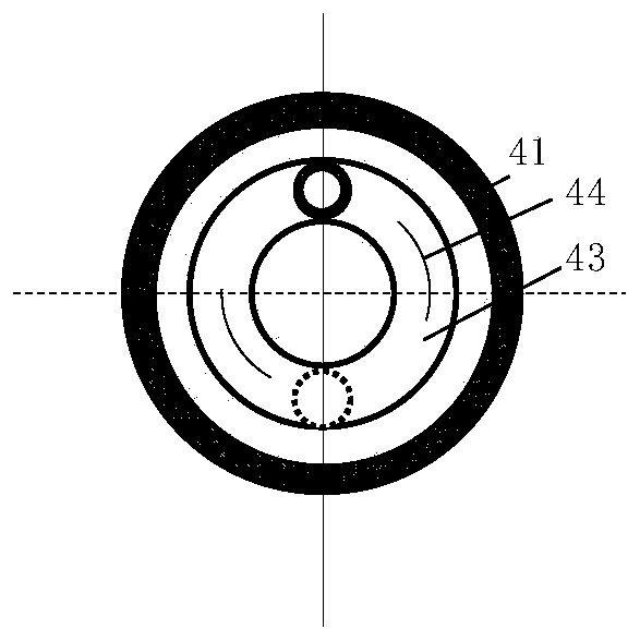
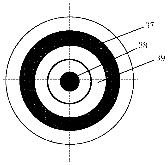
[0071] The structural representation of the fly ash reinforced foam forming device provided by the invention is as follows figure 1 As shown, it includes fly ash and foaming agent mixer 1, fly ash dispersion liquid splitter 12 (fly ash dispersion liquid splitter cavity 15), fly ash primary ultrasonic disperser 26, fly ash two Level ultrasonic disperser 32, fly ash three-level ultrasonic disperser 37, fly ash reinforced foam generator 41. The top of the fly ash and foaming agent mixer tank body 1 is provided with a feed inlet 2, a first injection port 9 of the foaming agent solution and a mixing agitator (comprising a mixing and stirring motor, a mixing and stirring rotating shaft 3 and a mixing and stirring paddle 4 ), the bottom is in communication with the first circulating pump 7 through the fly...


PUM

PropertyMeasurementUnit
Diameteraaaaaaaaaa
Lengthaaaaaaaaaa
The inside diameter ofaaaaaaaaaa

Abstract

The invention discloses a fly ash reinforced foam forming device for an oil field and application thereof. In the forming device, the top of a coal ash-foaming agent mixer is provided with a feed port, a first injection port of a foaming agent solution and a mixing stirrer, and the bottom of the coal ash-foaming agent mixer is communicated with a coal ash dispersion liquid flow divider through a coal ash mixed liquid discharging pipe; a flow-dividing stirrer is arranged at the top of the fly ash dispersion liquid flow divider; a first-stage dispersion liquid discharging pipe, a second-stage dispersion liquid discharging pipe and a third-stage dispersion liquid discharging pipe are arranged on the side wall of the coal ash dispersion liquid flow divider in the radial direction of the side wall and communicated with a coal ash reinforced foam generator; and a gas injection port and a foam generator discharging port are formed in the coal ash reinforced foam generator. The fly ash reinforced foam forming device overcomes the defect that the particle size of fly ash in fly ash reinforced foam cannot be controlled in conventional devices is overcome, realizes rapid and efficient flow division of fly ash dispersion liquids with different particle sizes, and can form a foam slug carrying fly ash with different particle sizes in one-shot construction, thereby realizing profile controlswitching between a near wellbore area and a far wellbore.

Description

technical field [0001] The invention relates to a fly ash reinforced foam forming device for oil fields and an application thereof, belonging to the technical field of fly ash solid waste utilization technology equipment and oil and gas field development engineering. Background technique [0002] Foam fluid flooding technology is an important means to enhance oil recovery, the formation of foam helps to control CO 2 Etc. gas displacement agent mobility in the reservoir, increase CO 2 and other greenhouse gas geological storage and oil displacement capabilities. A large number of applications have shown that foam has a significant effect in plugging high-permeability layers, adjusting water injection profiles, and improving oil washing efficiency. Foam can effectively increase the apparent viscosity of the fluid, thereby increasing the oil-water mobility ratio and increasing the swept volume; at the same time, the surfactant in the foaming liquid can reduce the interfacial ...

Claims


Application Information

Patent Timeline
IPC IPC(8): B01F13/10B01F15/02B01F3/04E21B43/22
CPCE21B43/16B01F23/291B01F33/821B01F35/717
Inventor 吕其超郑嵘周同科张娟董朝霞林梅钦杨子浩舒成龙
Owner CHINA UNIV OF PETROLEUM (BEIJING)
Why Eureka
Try Eureka