Crown repair adjacent gap dynamometer for stomatology department

A technology of stomatology and dynamometer, which is applied in the field of oral measuring equipment, can solve the problems that it is impossible to objectively obtain whether an adjacent gap is suitable, the denture crown and adjacent teeth are easy to be impacted by food, and affect the use of patients, so as to improve the convenience , Prevent errors and prevent equipment from malfunctioning

Inactive Publication Date: 2020-03-24
陈丕铭
View PDF0 Cites 0 Cited by
  • Summary
  • Abstract
  • Description
  • Claims
  • Application Information

AI Technical Summary

Problems solved by technology

[0002] Dental surgeons generally use dental floss when installing fixed crowns on patients, and feel the closeness of contact between the restoration and the restoration, or between the restoration and the adjacent teeth, to judge whether the new crown is related to the new crown, or whether the new crown is related to the adjacent teeth. Whether the adjoining gap between them is tight. When the doctor thinks that the adjoining relationship is normal, he will use adhesive to permanently bond the crown to the abutment tooth. A loose adjoining relationship may cause easy gaps between the crown and the adjacent teeth. Impacted food will affect the patient's use, and the tight adjacency will cause the patient to feel uncomfortable. Since the existing technology relies entirely on the doctor's touch, it is impossible to objectively obtain a value to judge whether the adjoining gap is appropriate

Method used


Image

  • Crown repair adjacent gap dynamometer for stomatology department
  • Crown repair adjacent gap dynamometer for stomatology department
  • Crown repair adjacent gap dynamometer for stomatology department

Examples


Embodiment Construction

[0026] The following will clearly and completely describe the technical solutions in the embodiments of the present invention with reference to the accompanying drawings in the embodiments of the present invention. Obviously, the described embodiments are only some, not all, embodiments of the present invention. Based on the embodiments of the present invention, all other embodiments obtained by persons of ordinary skill in the art without making creative efforts belong to the protection scope of the present invention.

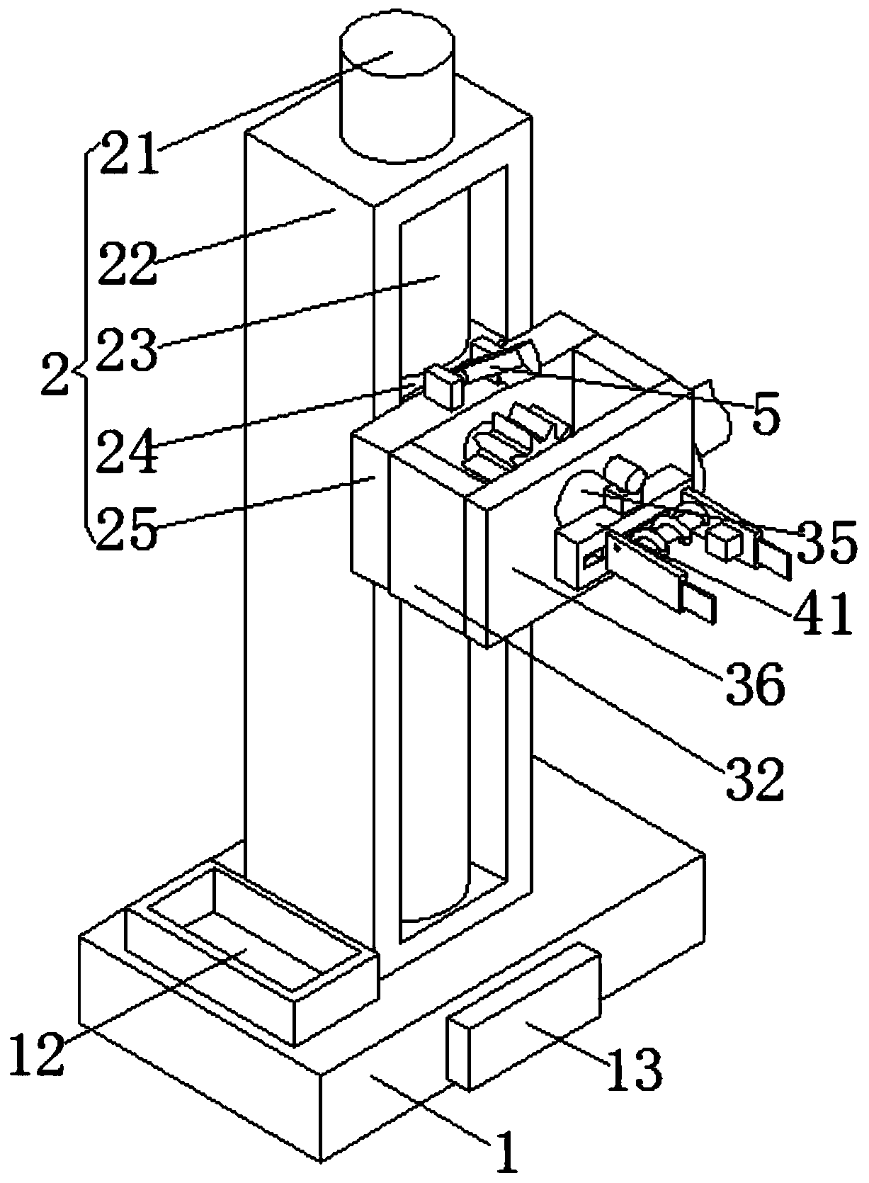
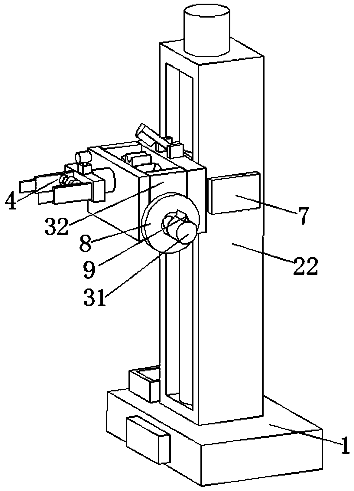
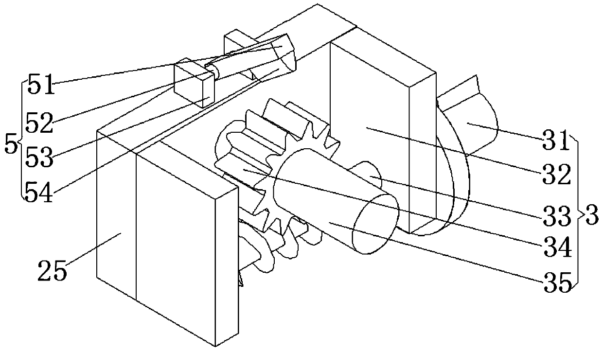
[0027] see Figure 1-4 , the present invention provides a technical solution: a dental crown restoration adjacent gap dynamometer, including a base plate 1, a lifting unit 2, a rotating unit 3 and a controller 13;

[0028] Bottom plate 1: a controller 13 is provided in the middle of the front side of the bottom plate 1;

[0029]Lifting unit 2: The lifting unit 2 includes a motor 21, a fixed block 22, a lead screw 23, a movable block 24 and a mounting plate 25...


PUM


Abstract

The invention discloses a crown repair adjacent gap dynamometer for a stomatology department. The crown repair adjacent gap dynamometer comprises a bottom plate, a lifting unit, a rotating unit and acontroller. The controller is arranged in the middle of the front side surface of the bottom plate. The lifting unit comprises a motor, a fixed block, a lead screw, a movable block and a mounting plate. The bottom end of the fixed block is connected with the middle part of the upper surface of the bottom plate. A groove is formed in the front side of the fixed block. A lead screw is rotationally connected with the inside groove. The bottom end of the motor is connected with the top end of a fixed block. An output shaft of the motor is connected with the top end of the lead screw. The movable block is slidably connected with the groove in the front side of the fixed block. A screw hole in the side of the movable block is in threaded connection with the lead screw. The front side of the movable block is connected with the middle of the rear side of the mounting plate. A rotating unit is arranged on the front side of the mounting plate. A fixed unit is arranged on the top end of the mounting plate. The crown repair adjacent gap dynamometer for the stomatology department has the advantages of simple structure, convenient use and accurate measurement.

Description

technical field [0001] The invention relates to the technical field of oral cavity measuring equipment, in particular to a force measuring instrument for the adjacent gap for dental crown restoration. Background technique [0002] Dental surgeons generally use dental floss when installing fixed crowns on patients, and feel the closeness of contact between the restoration and the restoration, or between the restoration and the adjacent teeth, to judge whether the new crown is related to the new crown, or whether the new crown is related to the adjacent teeth. Whether the adjoining gap between them is tight. When the doctor thinks that the adjoining relationship is normal, he will use adhesive to permanently bond the crown to the abutment tooth. A loose adjoining relationship may cause easy gaps between the crown and the adjacent teeth. Impacted food will affect the patient's use, and the tight adjacent relationship will cause the patient's discomfort. Since the existing techn...

Claims


Application Information

Patent Timeline
Patent Type & Authority Applications(China)
IPC IPC(8): A61C19/04A61C19/00
CPCA61C19/00A61C19/04
Inventor 陈丕铭
Owner 陈丕铭
Why Eureka
Try Eureka