
Fruit juicing device

A fruit and juicing technology, which is applied in the field of fruit juicing devices, can solve the problems of large waste of raw materials and insufficient juicing.

Inactive Publication Date: 2020-03-24
胡文凤
View PDF6 Cites 0 Cited by
  • Summary
  • Abstract
  • Description
  • Claims
  • Application Information

AI Technical Summary

Problems solved by technology

At present, there are still methods of manual juice extraction for fruit juice, and machine juice extraction is also widely used, but no matter whether it is punching juice extraction equipment or screw juice extraction equipment, there are problems that the juice is not thorough enough and the waste of raw materials is large.

Method used


Image

  • Fruit juicing device
  • Fruit juicing device
  • Fruit juicing device

Examples


Embodiment 1

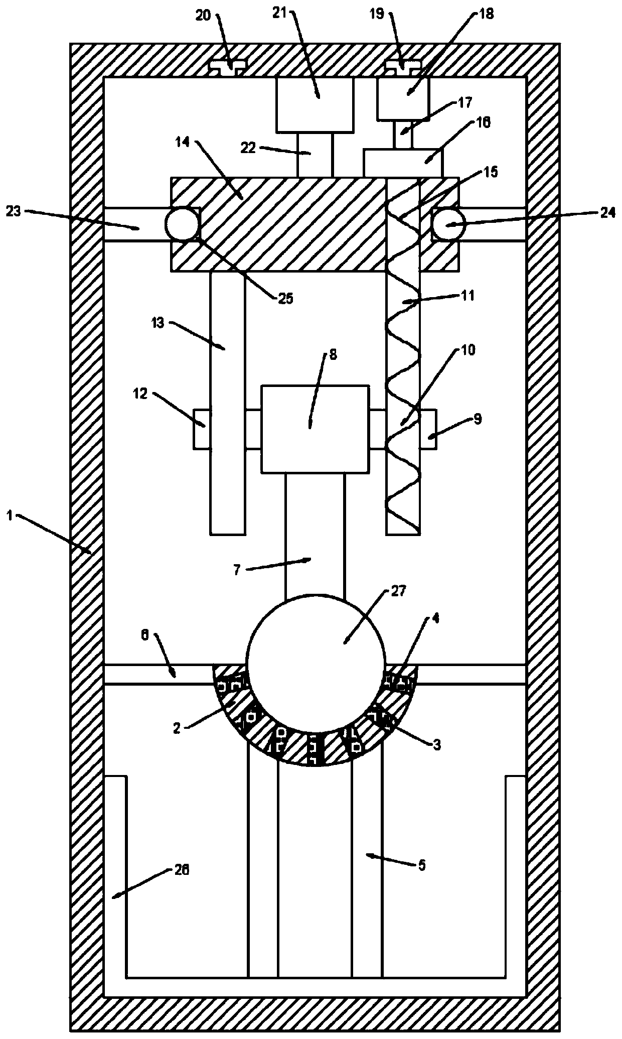
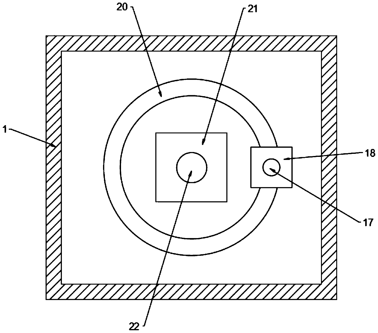
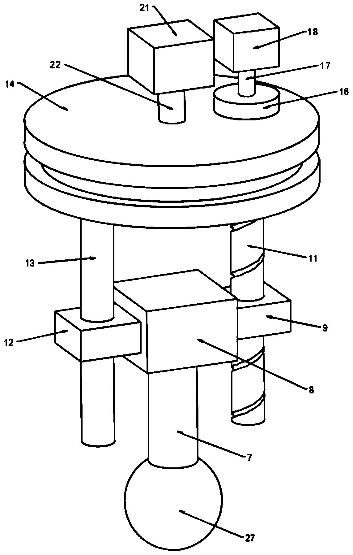
[0020] see Figure 1~3 , in the embodiment of the present invention, a kind of fruit juicer, comprises box body 1, and described box body 1 is provided with juicer groove 2, and the top of juicer groove 2 is arranged with juicer hammer 27, and described juicerer hammer 27 The upper end is fixedly connected with the connecting rod 7, the upper end of the connecting rod 7 is fixedly connected with the connecting block 8, the right side of the connecting block 8 is provided with a right bump 9, the right bump 9 is provided with a screw hole 10, and the screw hole 10 is threadedly connected with a screw rod 11 , the left end of the connecting block 8 is fixedly connected with a left bump 12, a slide bar 13 is slidably installed on the left bump 12, a disc 14 is arranged in the box body 1, and the disc 14 is located above the connecting block 8, and the slide bar The upper end of 13 is fixedly connected to the lower end of the disc 14, the right side of the disc 14 is provided with...

Embodiment 2

[0025] In order to prevent the juicing tank 2 from tilting due to the impact of the juicer hammer 27, this embodiment is further improved on the basis of embodiment 1. The end of the rod 6 is fixedly connected to the inner side wall of the box body 1, and the two ends of the juice extracting tank 2 are limited and fixed by the fixed rod 6, so as to prevent the juice extracting tank 2 from tilting.

[0026] The working principle of this embodiment is: in order to prevent the juicing tank 2 from tilting due to the impact of the juicer hammer 27, a fixed rod 6 is fixedly connected to both ends of the juicer tank 2, and the end of the fixed rod 6 is fixedly connected to the box body 1. On the inner side wall, the two ends of the juice extraction tank 2 are limited and fixed by the fixing rod 6, which can prevent the juice extraction tank 2 from tilting.

[0027] To sum up, by setting the screw 11, the screw 11 can be rotated, and under the action of the screw hole 10, the juicer h...


PUM


Abstract

The invention discloses a fruit juicing device. The device comprises a box body, a juicing groove is formed in the box body; a juicing hammer is arranged above the juicing groove; the upper end of thejuicing hammer is fixedly connected with a connecting rod; connecting blocks are fixedly connected to the upper ends of the connecting rods; a right bump is arranged on the right side of the connecting block; a screw hole is formed in the right convex block; the screw hole is in threaded connection with a screw rod; the left end of the connecting block is fixedly connected with a left protrudingblock. A sliding rod is mounted on the left convex block in a sliding manner; a disc is arranged in the box and located above the connecting block, the upper end of the sliding rod is fixedly connected to the lower end of the disc, a through hole is formed in the right side of the disc, the upper end of the screw penetrates through the through hole and is fixedly connected with a boss, a first motor is arranged at the top end in the box, and the lower end of the shaft rod is fixedly connected to the boss. By arranging the screw rod, the screw rod can be rotated, and the juicing hammer is driven to move up and down under the action of the screw hole, so that fruits in the juicing groove are juiced; and by arranging the screen, pulp can be blocked, and the quality of juice in the juice box is guaranteed.

Description

technical field [0001] The invention relates to the field of fruit processing, in particular to a fruit juice extractor. Background technique [0002] Fresh fruit is rich in nutrition, but its tissue is soft and contains more water, so it is easy to deteriorate due to the influence of various microbial parasites and physical and chemical factors. Fruit processing is a process in which fruits and berries are used as raw materials, processed into food by physical, chemical or biological methods to achieve the purpose of preservation. Fruits can be processed to improve fruit flavor, increase food value and economic benefits, and effectively prolong fruit supply time. [0003] Fruit juicing is a kind of fruit processing. As people like fruit juice drinks more and more, this fruit processing method of juicing will be more and more widely used. At present, there is still a manual way of juicing fruit, and machine juicing is also widely used, but no matter whether it is a punchin...

Claims


Application Information

Patent Timeline
Patent Type & Authority Applications(China)
IPC IPC(8): A47J19/02
CPCA47J19/02
Inventor 胡文凤
Owner 胡文凤
Learn More