
Novel door lock panel handle

A panel and handle technology, which is applied in the field of new door lock panel handles, can solve the problems of inability to open the handle, non-universal use, and reduced elasticity, so as to improve customer experience, increase universal adaptability, and improve service life.

Pending Publication Date: 2020-03-20
江苏东冠智能科技有限公司
View PDF0 Cites 0 Cited by
  • Summary
  • Abstract
  • Description
  • Claims
  • Application Information

AI Technical Summary

Problems solved by technology

[0003] The existing handle-type anti-theft door lock has a rotatable handle inside and a non-rotatable handle outside. Therefore, there are two structures in the panel handle and they are not common to each other, which leads to many types of panel handles. The difference between the left and right openings also makes the handles uncommon, which makes it difficult for consumers to distinguish and choose. Manufacturers have a wide variety of stocks and waste resources.
[0004] In addition, depending on the thickness of the door to be installed, the length of the internal square bar of the lock is also different, otherwise the opening function of the handle cannot be realized. In the traditional lock structure, the square bar is cut according to the thickness of the door at the installation site. The operation can only be done by specialized installers, which is difficult for ordinary users, and the cutting of square rods makes the whole installation process cumbersome and time-consuming
[0005] For the reset of the inner handle of the panel handle, the traditional structure is to use a torsion spring to cooperate with some limiting parts to realize the reset. However, after the torsion spring is used for a period of time, its elastic force is greatly reduced, which makes the handle unable to be reset or opened. This requires Replacement of the entire panel handle increases the user's cost

Method used


Image

  • Novel door lock panel handle
  • Novel door lock panel handle
  • Novel door lock panel handle

Examples


Embodiment Construction

[0034] The technical solutions of the embodiments of the present invention will be clearly and completely described below in conjunction with the accompanying drawings of the present invention.

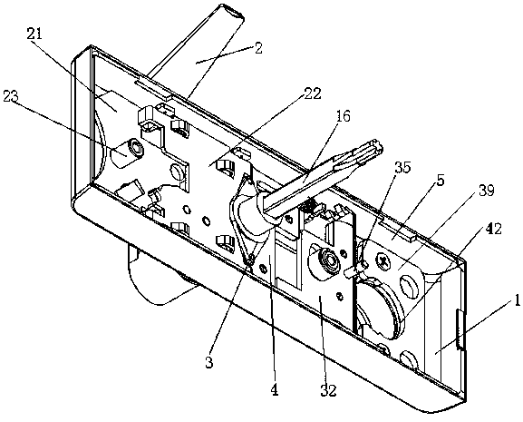
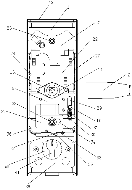
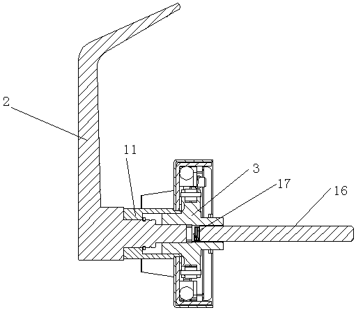
[0035] Such as Figure 1~3 As shown, a novel door lock panel handle disclosed by the present invention includes a panel 1, a handle 2 installed on the panel 1, a rhombus torsion angle 3, a toggle mechanism installed in the panel, a safety moving piece 4, and a rotation limiter. Position mechanism and adjustment mechanism, in which the toggle mechanism is located above the diamond-shaped torsion angle, and the safety movable piece is located below the rhombus-shaped torsion angle. The rotation limit mechanism is located under the insurance moving piece to limit its movement, and the adjustment mechanism is located under the rotation limit mechanism to adjust its position limit state.

[0036] Specifically, the panel is bent around to form side strips 5 so that the interior of the pane...


PUM


Abstract

The invention discloses a novel door lock panel handle. The novel door lock panel handle comprises a panel, a handle installed on the panel, a rhombic torsional angle, shifting mechanisms installed inthe panel, a safety mobile piece, a rotary limiting mechanism and an adjustment mechanism. The shifting mechanisms are located above the rhombic torsional angle. The safety mobile piece is located below the rhombic torsional angle. The rhombic torsional angle is driven by the handle to turn, the handle resets through the shifting mechanisms above and below, and the safety mobile piece, and at thesame time, the safety mobile piece is limited in movement by the rotary limiting mechanism below, and the rotary limiting mechanism is adjusted by the adjustment mechanism below in the limiting state.

Description

technical field [0001] The invention relates to a panel handle, in particular to a novel door lock panel handle. Background technique [0002] More common on the anti-theft door at present is to install the handle type anti-theft door lock, the panel handle of the handle type anti-theft door lock is directly connected with the lock body and controls the dead bolt work of the anti-theft door lock by controlling the rotation of the handle to realize the opening function. [0003] The existing handle-type anti-theft door lock has a rotatable handle inside and a non-rotatable handle outside. Therefore, there are two structures in the panel handle and they are not common to each other, which leads to many types of panel handles. The difference between the left and right openings also makes the handles uncommon, making it difficult for consumers to distinguish and choose, and manufacturers stock a wide variety of products, wasting resources. [0004] In addition, depending on the...

Claims


Application Information

Patent Timeline
IPC IPC(8): E05B13/00E05B9/00
CPCE05B9/002E05B13/002
Inventor 张季冬
Owner 江苏东冠智能科技有限公司
Learn More